Security door apparatus

A door device and door frame technology, which is applied to the suspension device of the wing leaf, the arrangement of the wing leaf, the direction of the window/door, etc.

A door device and door frame technology, which is applied to the suspension device of the wing leaf, the arrangement of the wing leaf, the direction of the window/door, etc.

CN1538031AInactive Publication Date: 2004-10-20BRANDE

Image

  • Security door apparatus
  • Security door apparatus
  • Security door apparatus

Examples


Embodiment

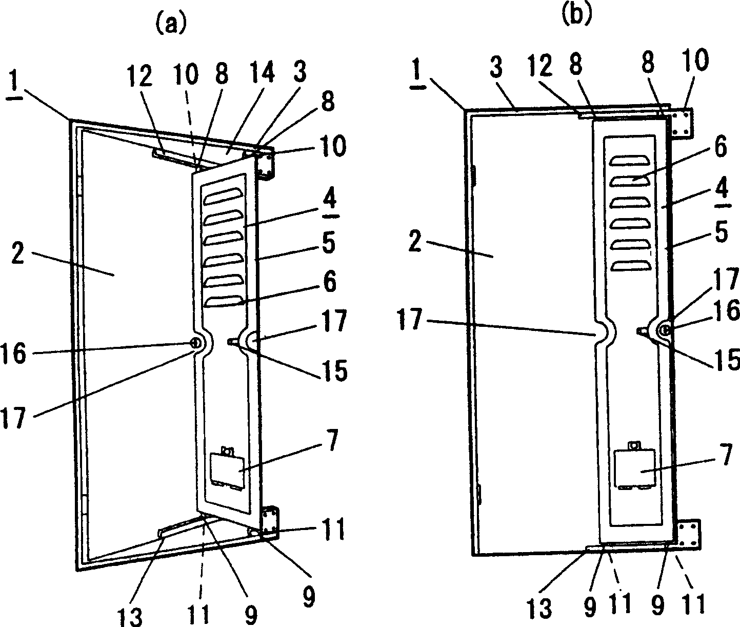
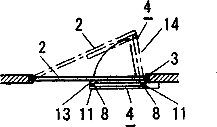
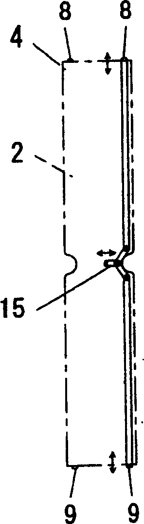
[0031] Figure 1 to Figure 4 An example of the door of the apartment etc. which shows this invention. The auxiliary door 4 with a width of 400mm is made of aluminum or iron, and the shutter 6 is integrally formed in the upper half of the surrounding frame 5, and a rectangular opening and closing window of 300×280mm that can be opened and closed from the inside is provided in the lower half 7. Install rod-shaped pivot parts 8, 9 that are approximately 1 / 2 of the height of the auxiliary door 4 inside the ends on both sides, and at the same time, as image 3 As shown, the inner ends of the pivot parts 8, 9 are stretched out toward the clutch lever 15, connected therewith and can be contracted freely.

[0032] And, the upper and lower pivot parts 8, 9 of the both ends of the auxiliary door 4 are respectively embedded in the sliding guides 12, 13 and the door frame which are arranged up and down on the inner surface of the plate-shaped door 2 and are "U"-shaped in section. 3 The ...


PUM


Abstract

The entrance security door apparatus has the object of providing security for the receiver in a condominium, etc., when the receiver must confirm an unexpected visitor, etc., by opening and closing a door such as entrance door. A locking tool is provided so that the door can be opened and closed to the side end side of a door opening frame, wherein the security door apparatus comprises: one side end part of an auxiliary door having a predetermined narrow width is connected to the inner side of the open / close side of the door and the other side end part of the auxiliary door is connected to the inner part of the side end of the open / close side of the door opening frame, and the auxiliary door is linked in such a manner that. When the door is opened, the auxiliary door functions as a barrier in the opening part between the door and the door opening frame. The auxiliary door is formed to have a lattice-shape shape, etc., so that the receiver can visually confirm the outside from the interior.

Description

technical field [0001] The present invention relates to a door device for security of apartments, detached houses and other gates in the field of buildings. Background technique [0002] In recent years, when home delivery services or door-to-door sales people visit apartments, detached houses, etc., once the door is opened, it is difficult to let out unwanted visitors, and occasionally there is a danger of encountering robbers. [0003] Therefore, there are also methods of checking the visitor through the peephole of the gate or a video camera, etc. However, it is not possible to easily and fully confirm the whole picture of the visitor, and when opening the door with a door chain, the opening of the door and the door frame is too small, Therefore, it is impossible to receive the deliveries, etc., and the door has to be opened, which makes it difficult to implement preventive measures. [0004] Therefore, patents related to guarding of gates were investigated. As a result...

Claims


Application Information

Patent Timeline
20 Oct 2004
Publication
CN1538031A
IPC
E06B3/36; E05C17/06; E05D15/26; E05D15/30; E05F11/52; E05F11/54; E05G7/00; E06B5/11; E06B7/28; E06B7/30; E06B9/02
CPC
E05G7/00; E05D15/262; E05F11/54; E05D15/30; E05Y2900/132; E06B5/11
Inventors
山本修作