
Aseptic battery with a removal cell cluster, the cell cluster configured for charging in a socket that receives a sterilizable battery

a technology of aseptic batteries and cell clusters, which is applied in the direction of electric vehicles, transportation and packaging, surgery, etc., can solve the problems of large size of known batteries and damage to cells in autoclaves, and achieve the effect of reducing dimensions

Active Publication Date: 2010-04-27
STRYKER CORP
View PDF11 Cites 752 Cited by
  • Summary
  • Abstract
  • Description
  • Claims
  • Application Information

AI Technical Summary

Benefits of technology

This patent is about a new and useful battery assembly that is designed to be aseptic (sterilizable). The assembly includes a small housing that can withstand the rigors of sterilization. The housing has a seal between the housing body and the cover that encloses the battery pack. This seal helps to minimize the size of the housing. The assembly also includes a battery pack that is removable and releasably seated in the housing. The battery pack contains one or more rechargeable cells that can be charged as if it were a sterilzable battery. The technical effects of this invention are that it provides a reliable and efficient solution for sterilizing battery assemblies, while maintaining their functionality and minimizing their size.

Problems solved by technology

One disadvantage of the above process is that exposure to the heat in the autoclave damages the cells.
However, the known batteries tend to be large in size.
Further, the cell clusters internal to these batteries are often known to require custom fixtures of sockets for attaching them to the complementary chargers to which they are fitted.

Method used


Image

  • Aseptic battery with a removal cell cluster, the cell cluster configured for charging in a socket that receives a sterilizable battery
  • Aseptic battery with a removal cell cluster, the cell cluster configured for charging in a socket that receives a sterilizable battery
  • Aseptic battery with a removal cell cluster, the cell cluster configured for charging in a socket that receives a sterilizable battery

Examples


Embodiment Construction

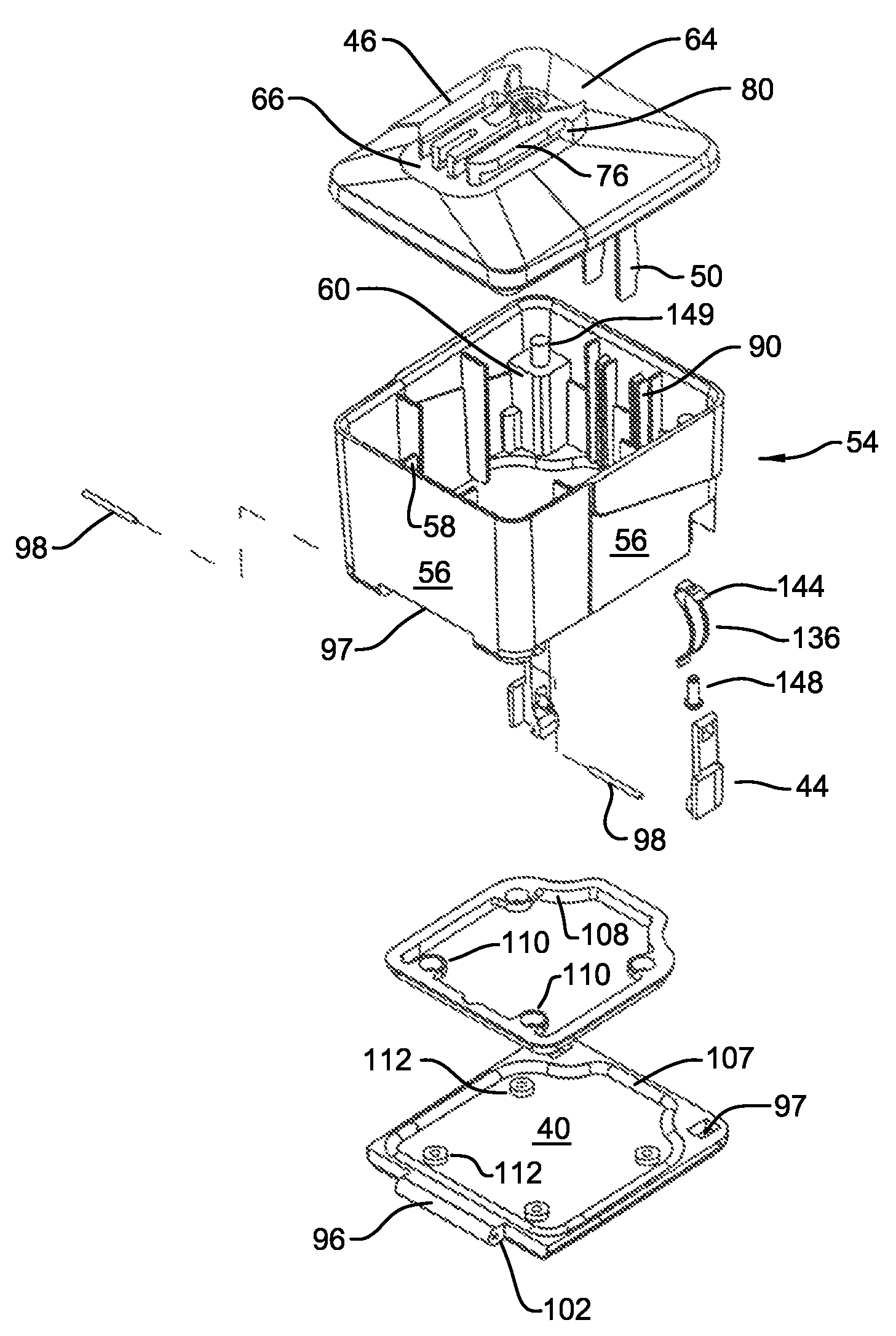
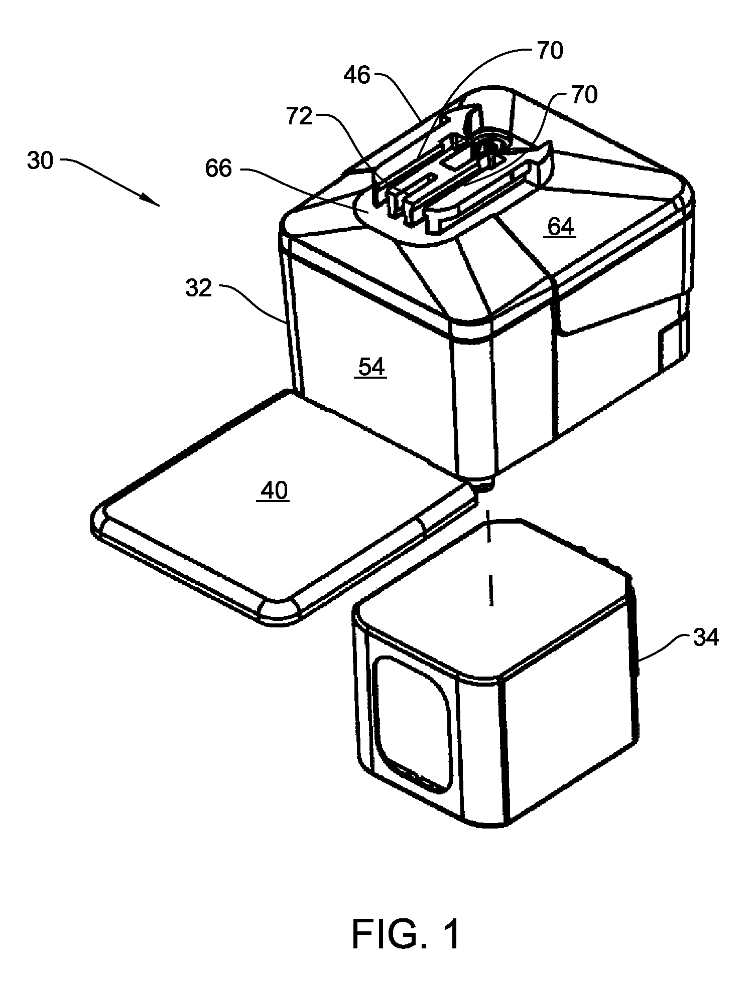
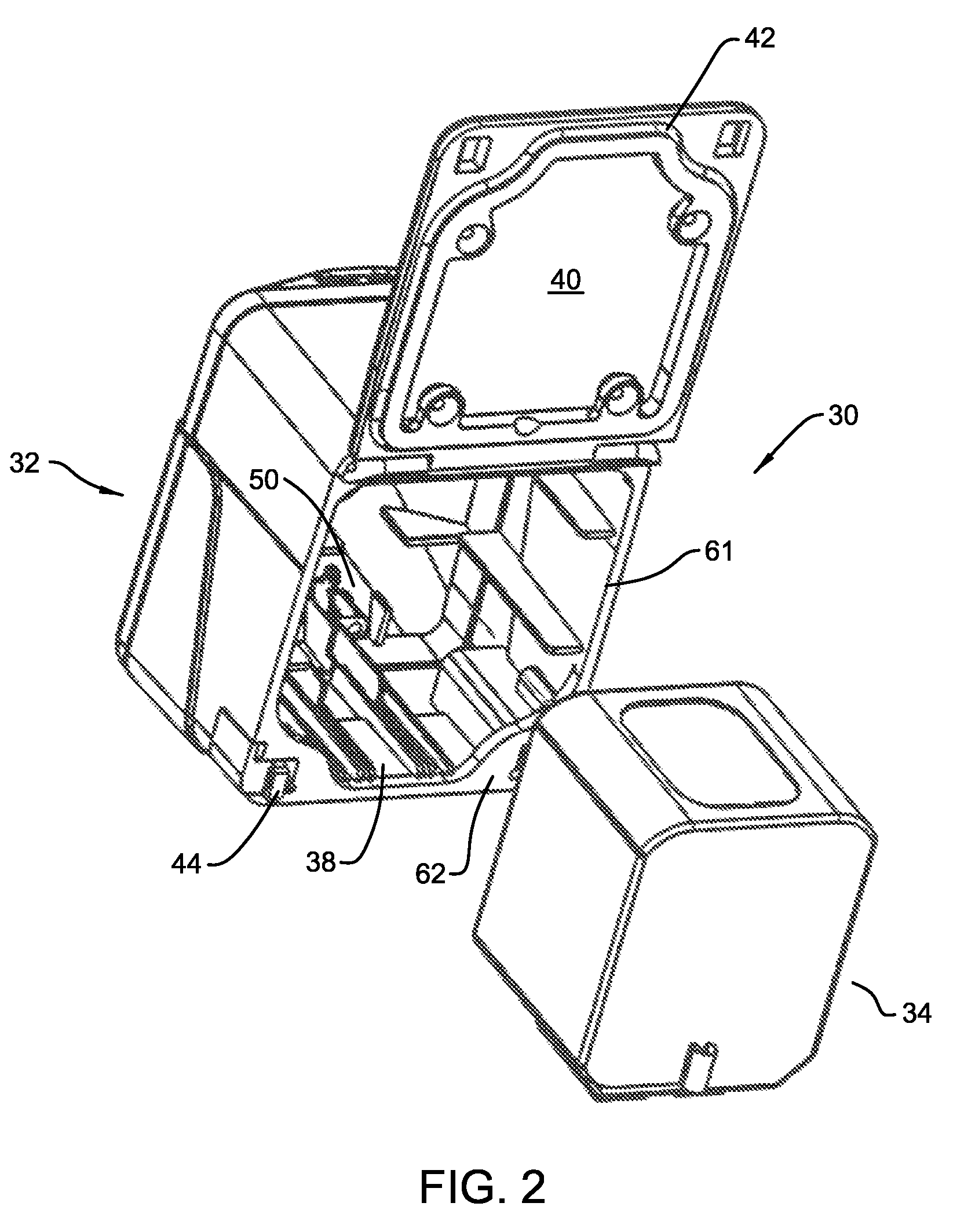
[0032]FIGS. 1-3 illustrate the basic components of the battery assembly 30 of this invention. Specifically, battery assembly 30 includes a housing 32 in which a battery pack 34 is removably seated. Battery pack 34 includes a number of rechargeable cells 36 for storing electrical energy, charge. Housing 32 defines a chamber 38 in which the battery pack 34 is disposed. A cover 40 pivotally mounted to the rest of the housing 32 forms the base of the housing and, when closed, covers the chamber 38. A seal 42 is mounted to the cover 40. When cover 40 is closed, seal 42 presses around the adjacent chamber-defining panels of the housing 32 to form a barrier between the cover and the rest of the housing. Latches 44 mounted to the housing releasably hold the cover in the closed position.

[0033]The housing 32 and battery pack 34 are each provided with separate heads 46 and 48, respectively, (battery pack head best seen in FIG. 12.) As described below mounted to the individual housing and batte...


PUM


Abstract

A battery assembly with a housing that contains a removable battery pack. The housing, which is sterilizable, has a head designed to couple to a power consuming device. The battery pack, which is not sterilizable, contains at least one rechargeable cell. The battery pack has a head dimensioned to fit the same charger socket that can receive a sterilizable battery. The battery pack has contacts that abut charger contacts. The housing has internal contacts. Collectively, the housing and battery pack are shaped so that, when the battery pack seats in the housing, the battery pack contacts abut the housing internal contacts. The housing internal contacts are connected to the housing external contacts for supply power to the power consuming device. A cover selectively holds the battery pack in the housing chamber.

Description

FIELD OF THE INVENTION[0001]This invention is generally related to rechargeable aseptic battery assembly. More particularly, this invention is related to an aseptic battery assembly with a removable cell cluster that is simple to use.BACKGROUND OF THE INVENTION[0002]A battery often energizes a powered surgical tool used in an operating room to perform a surgical procedure. The use of a battery eliminates the need to provide a power cord connected to an external power source. The elimination of the power cord offers several benefits over corded surgical tools. Surgical personnel using this type of tool do not have to concern themselves with either sterilizing a cord so that it can be brought into the sterile surgical field surrounding the patient or ensuring that, during surgery, an unsterilized cord is not inadvertently introduced into the sterile field. Moreover, the elimination of the cord results in the like elimination of the physical clutter and field-of-view blockage the cord ...

Claims


Application Information

Patent Timeline
Patent Type & Authority Patents(United States)
IPC IPC(8): H02J7/00
CPCH02J7/0042A61B2017/00734H02J2310/23
Inventor POWELL, MATTGERBER, VAUGHN R.DUIS, RONALD
Owner STRYKER CORP
Learn More