Display apparatus

a technology of display apparatus and display screen, which is applied in the direction of television systems, electric apparatus casings/cabinets/drawers, instruments, etc., can solve the problems of difficult to reduce the thickness of the display screen, and achieve the effect of diffuser heat generated

Active Publication Date: 2014-08-19
SATURN LICENSING LLC
View PDF20 Cites 787 Cited by
  • Summary
  • Abstract
  • Description
  • Claims
  • Application Information

AI Technical Summary

Benefits of technology

[0020]As described above, the present invention provides a novel and improved display apparatus which can effectively diffuse heat generated by a heat source such as an LED when the heat source is arranged at aside surface of at least one side of a display panel.

Problems solved by technology

Therefore, it used to be difficult to reduce the thickness of the LCD.

Method used


Image

  • Display apparatus
  • Display apparatus
  • Display apparatus

Examples


Embodiment Construction

[0069]Hereinafter, preferred embodiments of the present invention will be described in detail with reference to the appended drawings. Note that, in this specification and the drawings, elements that have substantially the same function and structure are denoted with the same reference signs, and repeated explanation is omitted.

[0070]A preferred embodiment of the present invention will be explained in detail in the order listed below.

[0071][1] Explanation about a liquid crystal display apparatus according to an embodiment of the present invention

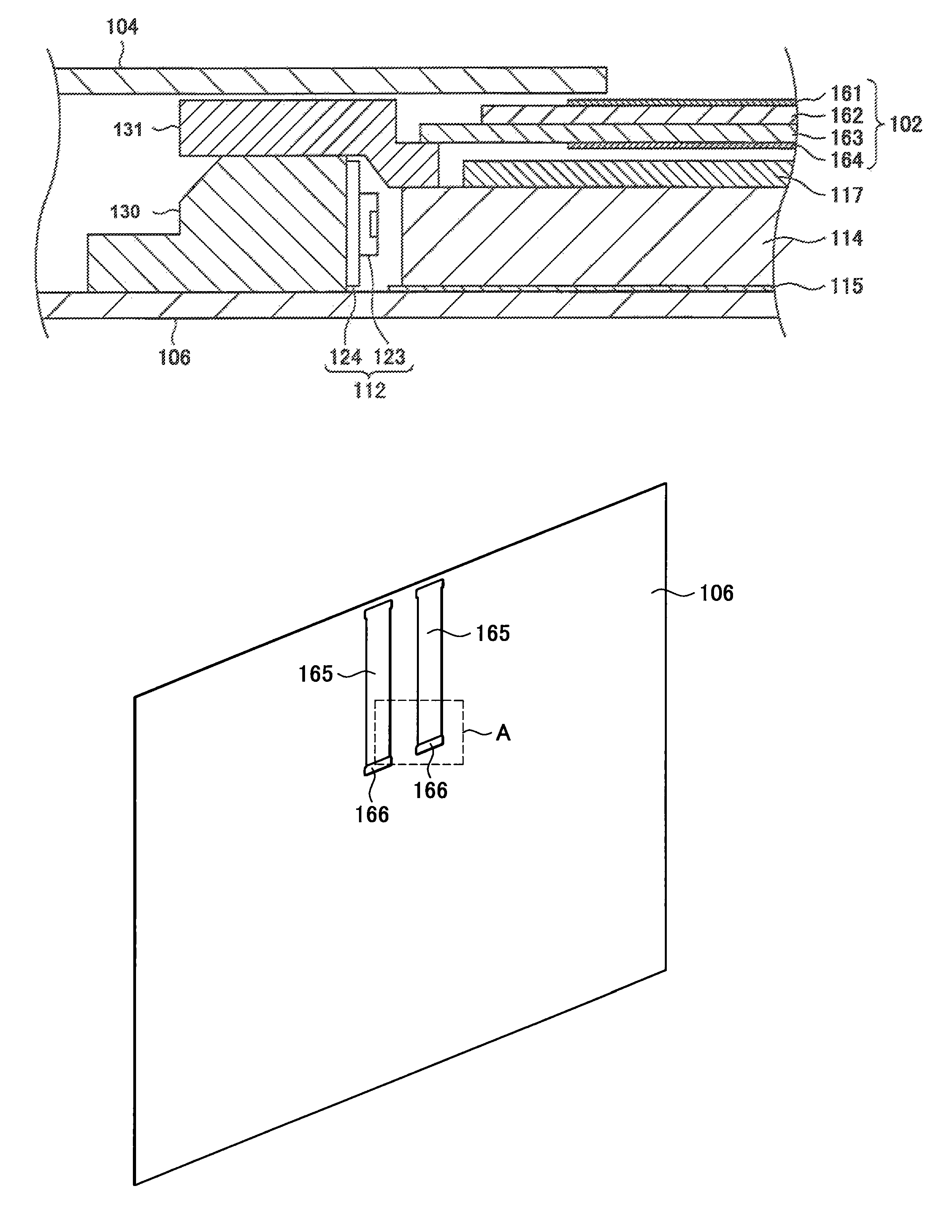
[0072][2] Explanation about heat radiation structure in a liquid crystal display apparatus according to an embodiment of the present invention

[0073][3] Explanation about structure of a liquid crystal display apparatus according to an embodiment of the present invention

[0074][4] Conclusion

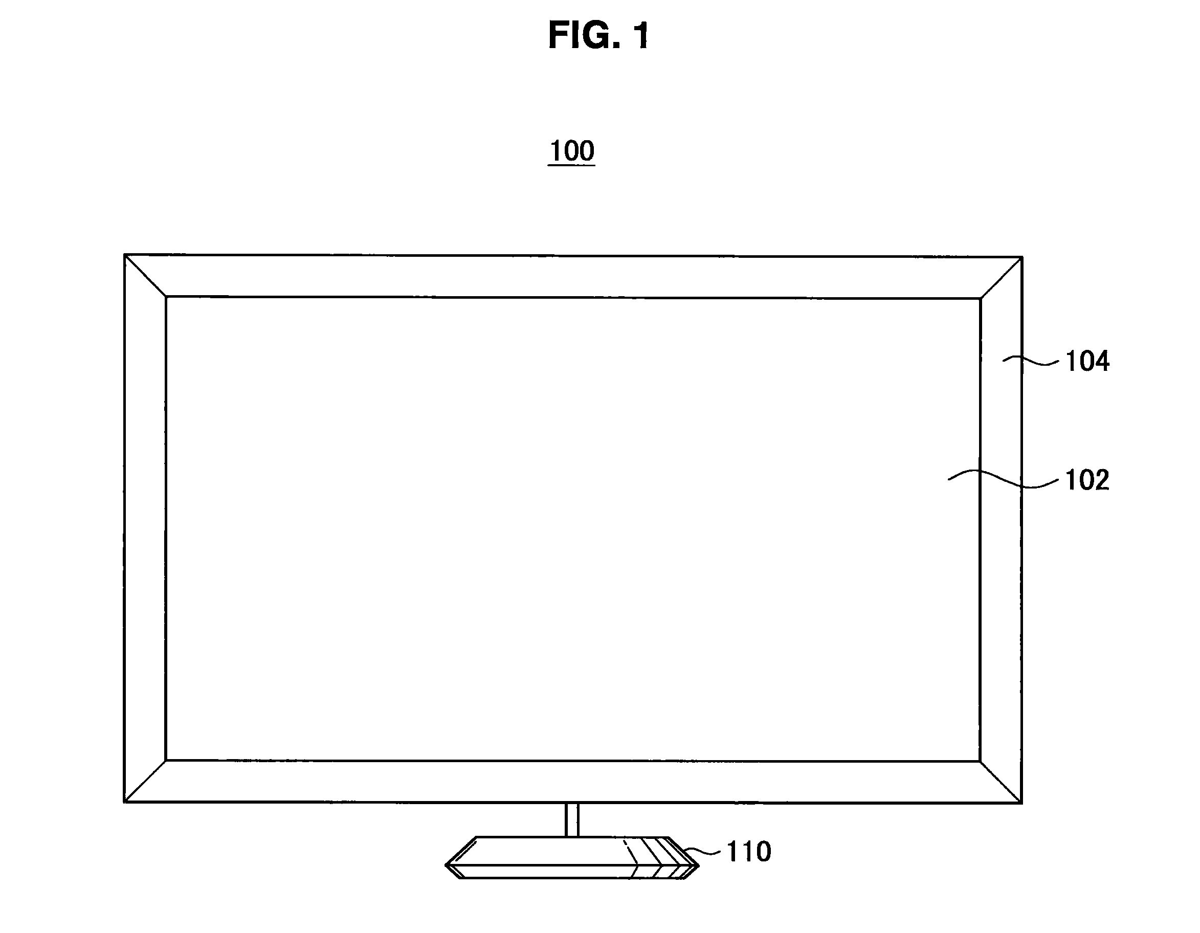
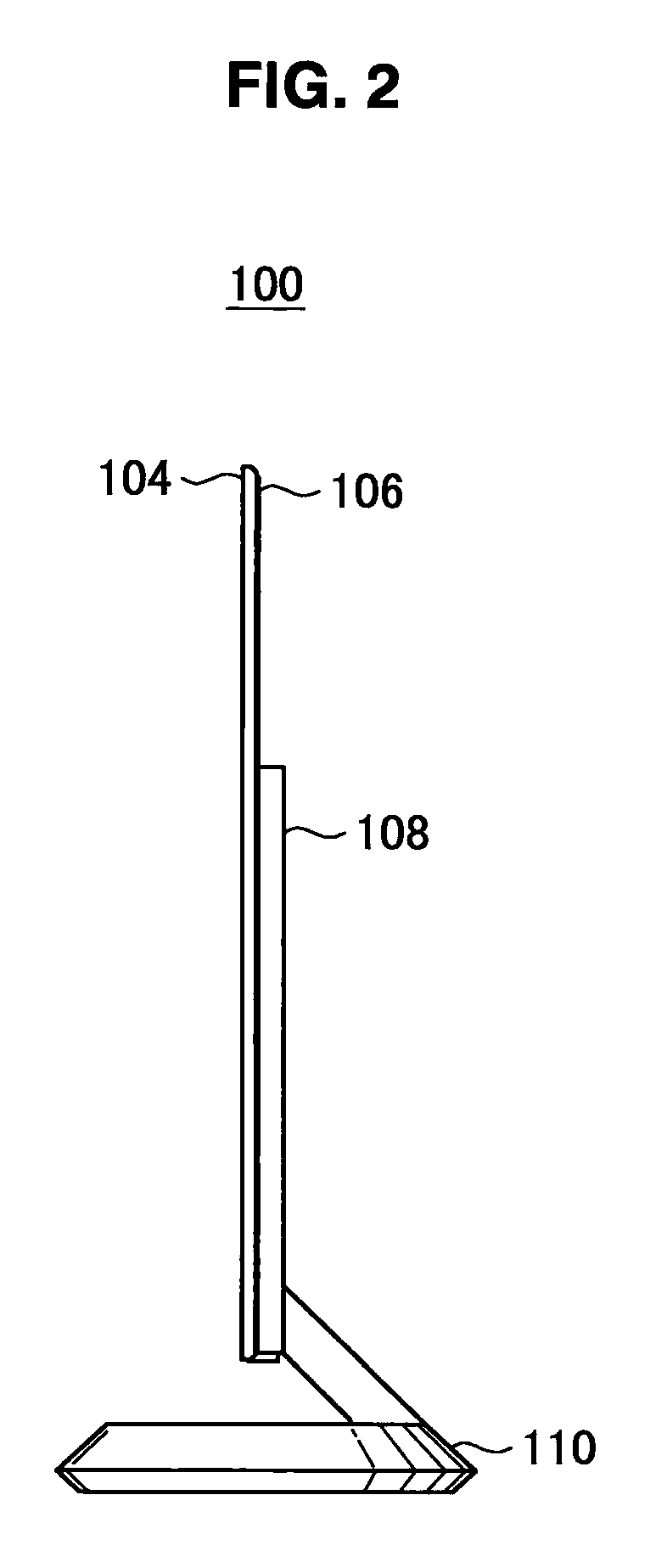
[0075][1] Explanation About a Liquid Crystal Display Apparatus According to an Embodiment of the Present Invention

[0076]First, an external appearance of a l...


PUM

PropertyMeasurementUnit
refractive indexaaaaaaaaaa
thermal conductivityaaaaaaaaaa

Abstract

Provided is a display apparatus including a display panel for displaying an image, a heat source arranged at a side surface of at least one side of the display panel, a heat absorbing section for absorbing heat generated by the heat source, a back surface plate arranged at a back surface side of the display panel and made of a metal, a portion of the back surface plate being in close contact with the heat absorbing section, a front surface plate arranged at a front surface side of the display panel and made of a metal, and a middle chassis arranged between the front surface plate and the heat absorbing section.

Description

TECHNICAL FIELD[0001]The present invention relates to a display apparatus.BACKGROUND ART[0002]A liquid crystal display (LCD: Liquid Crystal Display) arranged in a liquid crystal display apparatus in the related art includes, e.g., a liquid crystal panel having a color filter substrate colored in red, green, and blue, a liquid crystal layer, and the like, and a backlight arranged at a back surface side of the liquid crystal panel.[0003]In the liquid crystal display apparatus, voltages are changed to control twists of liquid crystal molecules in the liquid crystal layer, and white light emitted by the backlight passes through the liquid crystal layer according to the twists of the liquid crystal molecules, and then passes through the color filter colored in respective colors. Since the white light emitted by the backlight passes through the color filter, the white light is colored in red, green, and blue, whereby an image is displayed.[0004]In the past, CCFL (Cold Cathode Fluorescent ...

Claims


Application Information

Patent Timeline
Patent Type & Authority Patents(United States)
IPC IPC(8): G02F1/1335G02F1/1333H05K7/20
CPCG02F1/133308G02F2001/133628G02F1/133382G02F1/133628H04N5/64G02F1/133317H05K7/20G02F1/13332G02F1/133302G02F1/133314G02B6/0051G02B6/0085G02F1/133528G02F1/1339
Inventor FUJII, HIROAKINAGATANI, SHINPEI
Owner SATURN LICENSING LLC
Why Eureka
Try Eureka