Screen and image projection apparatus

a projection apparatus and screen technology, applied in the field of screen and image projection apparatus, can solve the problems of large and complicated vibrating mechanism, high power requirement, and difficult to vibrate the screen b>60/b>, and achieve the effect of smooth displacement and reliably reducing the amount of speckle and scintillation

Inactive Publication Date: 2007-07-26
SONY CORP
View PDF12 Cites 28 Cited by
  • Summary
  • Abstract
  • Description
  • Claims
  • Application Information

AI Technical Summary

Benefits of technology

[0014]To reduce speckle and scintillation, diffusing the light is effective. However, as the amount of diffusion is increased, the gain of light emitted from the light source decreases and the resolution decreases.
[0028]In addition, by moving the diffuser plate relative to the securing member that directly or indirectly supports the diffuser plate, the diffuser plate can easily perform a circular motion or an elliptic motion with no stop points. Consequently, the amount of speckle and scintillation can be reliably reduced.

Problems solved by technology

However, to vibrate the entire screen 60, significantly high power is needed, and therefore, it is difficult to vibrate the screen 60.
To vibrate the entirety of a screen of such a large rear-projection television set, a large and complicated vibrating mechanism is needed.
However, it is very difficult to apply such a mechanism to consumer electronic appliances.
However, as the amount of diffusion is increased, the gain of light emitted from the light source decreases and the resolution decreases.
However, even in such a structure, the speckle cannot be sufficiently reduced when a laser is used for the light source.

Method used


Image

  • Screen and image projection apparatus
  • Screen and image projection apparatus
  • Screen and image projection apparatus

Examples


Embodiment Construction

[0039]Exemplary embodiments of the present invention are described below with reference to the accompanying drawings. However, it should be noted that the present invention is not limited thereto.

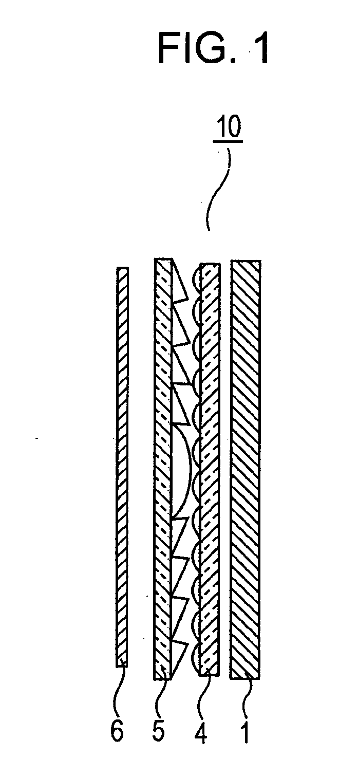
[0040]FIG. 1 is a schematic cross-sectional view of a screen according to an embodiment of the present invention. In general, as shown in FIG. 1, a screen used for an image projection apparatus, such as a rear-projection television set, includes, in the following order from a viewer side, a diffuser plate 1, a lenticular lens unit 4, a Fresnel lens unit 5, and a diffuser plate 6.

[0041]In the present embodiment, the diffuser plate 6 is disposed closer to a light source than the Fresnel lens unit 5. The diffuser plate 6 is disposed in a securing member (e.g., a housing) so as to be movable in two directions in the plane of the screen, that is, in two directions in the plane of the diffuser plate 6 by using an elastic member.

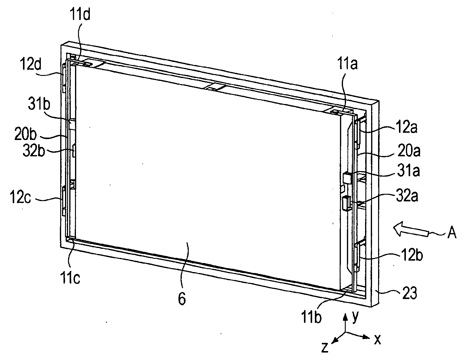
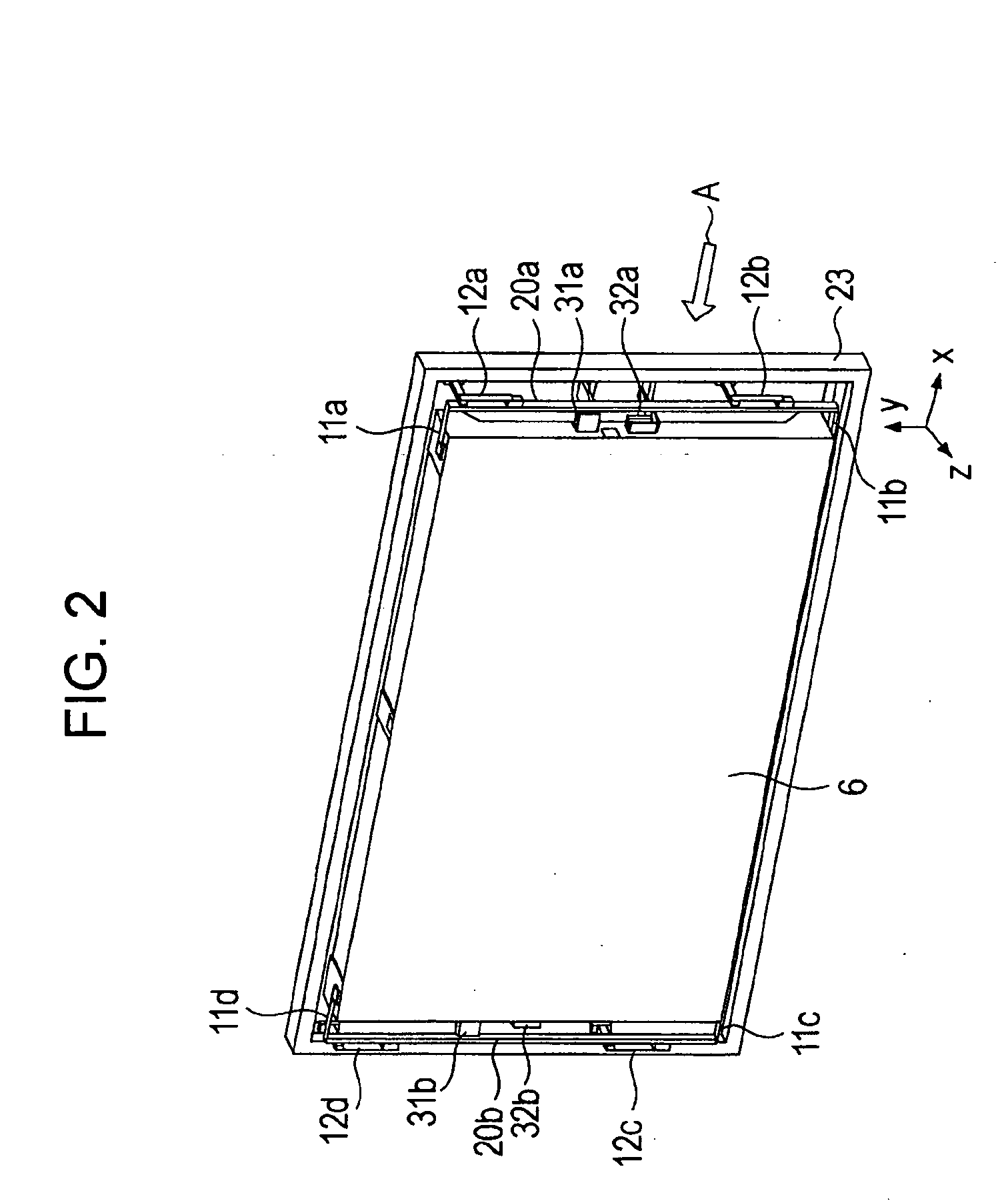
[0042]FIG. 2 is a schematic perspective view of the main portion of t...


PUM


Abstract

Light emitted from a light source is modulated and projected on a screen. The screen includes a securing member, a diffuser plate supported by the securing member using a plurality of elastic members, where the elastic members are disposed so that the diffuser plate is resiliently displaced in two directions in the plane of the diffuser plate, and a driving unit that moves the diffuser plate with respect to the securing member in the two directions in the plane of the diffuser plate.

Description

CROSS REFERENCES TO RELATED APPLICATIONS[0001]The present invention contains subject matter related to Japanese Patent Application JP 2006-016615 filed in the Japanese Patent Office on Jan. 25, 2006, the entire contents of which are incorporated herein by reference.BACKGROUND OF THE INVENTION[0002]1. Field of the Invention[0003]The present invention relates to a screen and an image projection apparatus used for, for example, projection television sets for modulating light that contains coherent light and that is emitted from a light source and projecting the light onto the screen.[0004]2. Description of the Related Art[0005]Image projection apparatuses (optical projectors) are known that illuminate a light modulation unit, such as a liquid crystal panel, a digital micromirror device (DMD), or a light modulation element using a diffraction grating, using an illumination unit so as to project light transmitted or reflected by the light modulation unit onto a screen using a projection ...

Claims


Application Information

Patent Timeline
Patent Type & Authority Applications(United States)
IPC IPC(8): G03B21/56G02B7/00G02B27/18G03B21/10G03B21/62G03B21/625H04N5/74
CPCG02B27/0933G02B27/48G03B21/62H04N5/7441H04N9/3105H04N9/3197H04N9/3141H04N9/3158H04N9/3161H04N9/3164H04N9/3129
Inventor SUGAWARA, YUTAKAKIKUCHI, HIROKI
Owner SONY CORP
Why Eureka
Try Eureka