Electrical power supply system for motor vehicle

a technology of electric power supply and motor vehicle, which is applied in the direction of electric generator control, dynamo-electric converter control, electric control, etc., can solve the problems of increasing the fuel consumption of the engine, the power supply voltage (i.e. voltage and voltage), and the engine torque load, so as to reduce the level of electrical power, reduce the amount of engine torque load, and reduce the effect of engine speed lowering

Active Publication Date: 2008-07-03
DENSO CORP
View PDF2 Cites 37 Cited by
  • Summary
  • Abstract
  • Description
  • Claims
  • Application Information

AI Technical Summary

Benefits of technology

[0042]In that way, when for example there is a sudden increase in the load power demand and this causes a momentary insufficiency of generated electrical power and hence power is discharged from the battery (i.e., the charge/discharge power is reduced) it becomes possible to temporarily reduce the level of electrical

Problems solved by technology

A correspondingly higher level of torque must be applied by the engine to the electric generator, to effect an increase in electrical power output, and this results in an increase in the engine fuel consumption.
However with the method described in reference document 1, the variations in the generated electrical power may be greater and occur more frequently than those which occur with a conventional type of voltage regulation, so that the problem arises that the power supply voltage (i.e., which is both the generator output voltage and the voltage of the vehicle battery) may vary rapidly, with large-scale fluctuations.
Problems such as flickering of the headlamps may thereby occur, which can be annoying to the vehicle driver.
Furthermore, due to such large-scale variations in electric generator output power, the level of engine torque that is absorbed by the generator will vary significantly.
In particular, when there is a sudden large increase in the torque load on the engine within a short period of time, a substantial lowe

Method used


Image

  • Electrical power supply system for motor vehicle
  • Electrical power supply system for motor vehicle
  • Electrical power supply system for motor vehicle

Examples


first embodiment

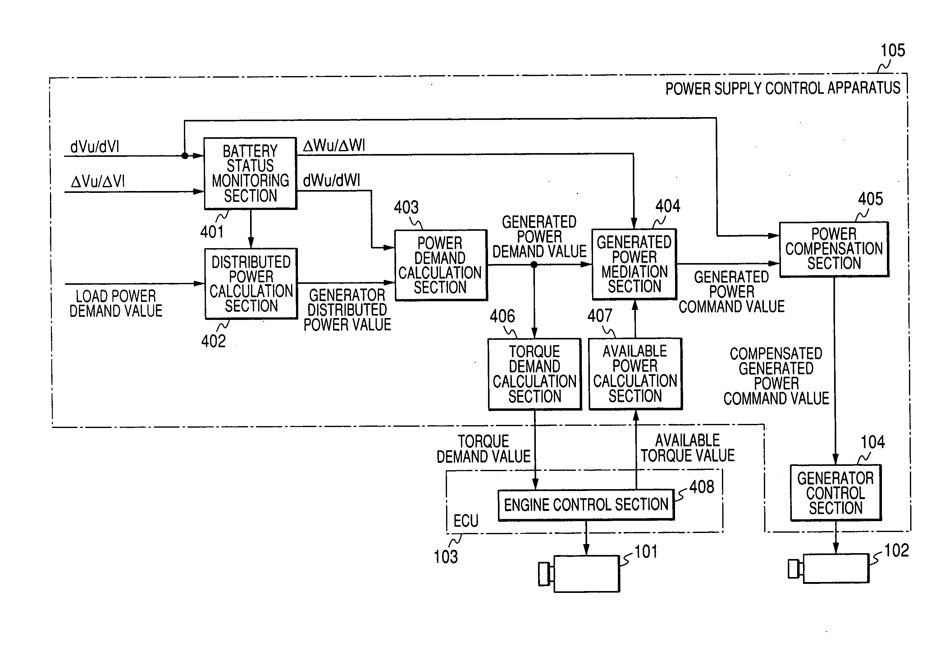
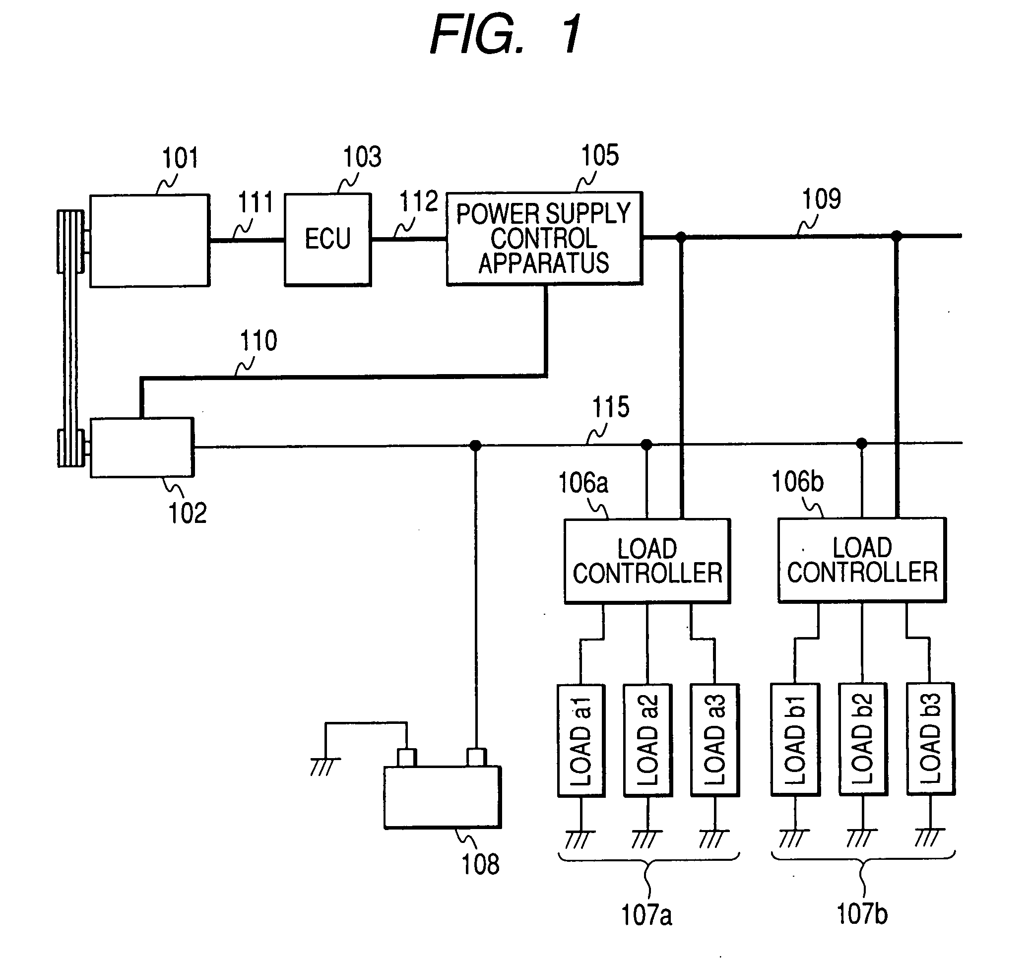
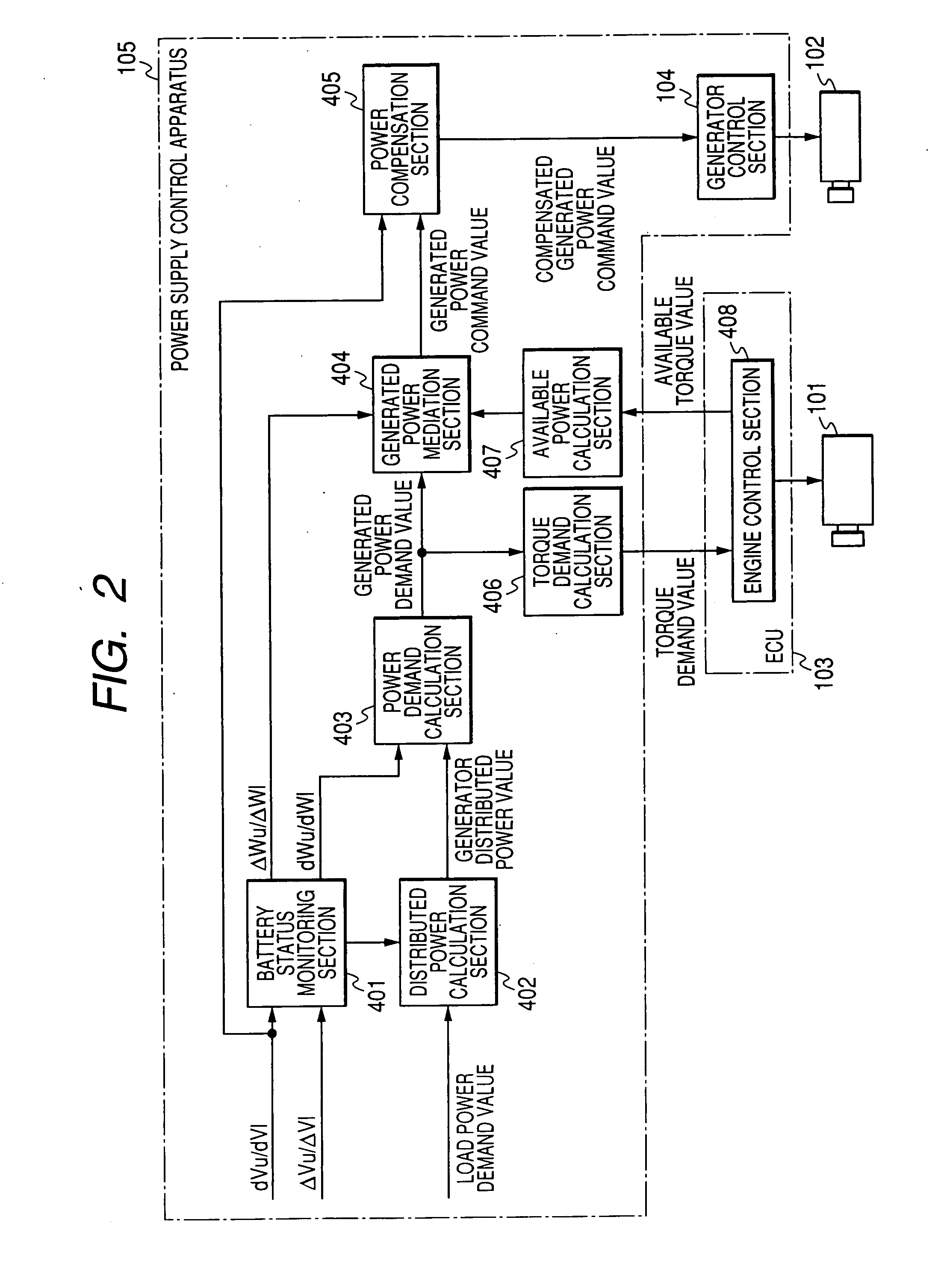
[0063]FIG. 1 shows the overall configuration of a first embodiment of a vehicle-use power supply system. As shown, the system includes an engine 101, an electric generator 102, an engine control unit (abbreviated to ECU in the following) 103, a power supply control apparatus 105, load control apparatuses 106a and 106b, and a battery (i.e., electrical storage battery) 108.

[0064]The electric generator (referred to in the following simply as the generator) 102 is driven for rotation by the engine 101, and supplies operating power to electrical loads 107a, 107b while also supplying electrical power to charge the battery 108. The power supply control apparatus 105 is connected to the generator 102, and to the load control apparatuses 106a and 106b which are respective controllers of the power supplied to the loads 107a and 107b. Information sent from the load control apparatuses 106a, 106b specifying the total amount of power that is currently required by the loads 107a, 107b will be ref...

second embodiment

[0143]FIG. 13 shows details of a power supply control apparatus 105A in a second embodiment of a vehicle-use power supply system. The second embodiment differs from the first embodiment only in that the power supply control apparatus 105 shown in FIG. 1 is replaced by the power supply control apparatus 105A, which differs from the power supply control apparatus 105 shown in FIG. 2 by further including a load power command value calculation section 409. The load power command value calculation section 409 receives the load power demand value (which is also inputted to the distributed power calculation section 402, as described for the first embodiment) and the generated power command value that is derived by the power generation mediation section 404 as described for the first embodiment. Based on these inputs, the load power command value calculation section 409 derives a command value of load power to be supplied by the load control apparatuses 106a, 106b to their loads 107a, 107b....

fourth embodiment

[0176]With the above embodiments, the ECU 103 and the power supply control apparatus 105 are connected by the communication line 112. However with a fourth embodiment as shown in FIGS. 19 and 20, the power supply control apparatus 105 is implemented within an ECU 103A. This provides the advantages that when control of the engine 101 and of the generator 102 is executed by the same microcomputer (or microcomputers), a common memory can be utilized, so that data communication between the engine control section 408 and the power supply control apparatus 105 can be performed at high speed. Improved synchronization can thereby be achieved between the level of torque being applied by the engine 101 to drive the generator 102 and the level of torque that is actually being absorbed by the generator 102.

[0177]It should be noted that as an alternative to the above, it would be equally possible to incorporate the engine control unit within the power supply control apparatus, or to incorporate ...


PUM


Abstract

A power supply control apparatus for controlling an electric generator of a vehicle limits the rate of change of a power supply voltage to a predetermined variation rate range, when the change is caused by operations to control the charge condition of the vehicle battery, and controls the generated power to match the drive torque applied by the engine to the generator. When the electrical load demand changes, the generated power is controlled to limit a resultant momentary change in the power supply voltage caused by an engine response delay, while minimizing a resultant momentary amount of engine speed variation.

Description

CROSS-REFERENCE TO RELATED APPLICATIONS[0001]This application is based on and incorporates herein by reference Japanese Patent First Application No. 2006-156745 filed on Jun. 6, 2006.BACKGROUND OF THE INVENTION[0002]1. Field of Application[0003]The present invention relates to an electrical power supply system (referred to in the following simply as a power supply system) installed in a motor vehicle, for regulating the electrical power produced from an electric generator that is driven by the vehicle engine.[0004]2. Description of Related Art[0005]Due to the increased amount of electrical equipment installed in motor vehicles in recent years, with an accompanying increase in the level of electrical power that must be generated for operating such equipment, it is becoming necessary for the engine-driven electric generator of a vehicle to produce a higher level of electrical power. A correspondingly higher level of torque must be applied by the engine to the electric generator, to ef...

Claims


Application Information

Patent Timeline
IPC IPC(8): F02D35/00H02P9/00H02P9/04
CPCB60R16/03H02J1/14F02D2200/503F02D41/021H02J2310/46F02D45/00B60R16/02
Inventor TANI, KEISUKEOBAYASHI, KAZUYOSHISENDA, TAKASHIYAMASHITA, YUKIHIROKURODA, DAISUKE
Owner DENSO CORP
Why Eureka
Try Eureka