Data transmitting and receiving apparatus and method for visible light communication

a data transmission and receiving apparatus technology, applied in the field of visible light communication, can solve the problems of difficult detection of phase information by the receiver, easy configuration of these methods, and drastic reduction of the average optical output power of the light source, so as to minimize the brightness reduction mitigate the flicker generation of the vlc light source

Inactive Publication Date: 2012-04-12
ELECTRONICS & TELECOMM RES INST
View PDF3 Cites 43 Cited by
  • Summary
  • Abstract
  • Description
  • Claims
  • Application Information

AI Technical Summary

Benefits of technology

[0013]The present invention has been made in an effort to provide data transmitting and receiving apparatus and method for visible light communication, which can minimize the brightness reduction of a VLC light source and mitigate the flicker generation of the VLC light source.

Problems solved by technology

In a VLC system using LED light sources, a transmitter generally uses the intensity modulation method or the on-off keying (00K) modulation method which varies the intensity of a visible light signal for modulating electrical data “0” and “1” because it is difficult for a receiver to detect the phase information of the transmitted signal and it is rather easy to configure these methods.
However, the OOK modulation method has a disadvantage that it drastically decreases the average optical output power of a light source.
However, these methods may cause an excess of allowable values for the LED light source driving and hence can shorten the lifetime of the light source.
Accordingly, when the OOK modulation is applied to the transmitter of the VLC system using the LED light source, it cannot provide the sufficient brightness that an LED light source can emit.
However, the NRZ-OOK and RZ-OOK methods, other than the Manchester-OOK method, may cause the flicker because the brightness of a visible light source representing “1” and “0” differs from each other, and the ratio of patterns “1” and “0” within an arbitrary data transmission slot varies with data combinations.

Method used


Image

  • Data transmitting and receiving apparatus and method for visible light communication
  • Data transmitting and receiving apparatus and method for visible light communication
  • Data transmitting and receiving apparatus and method for visible light communication

Examples


Embodiment Construction

[0042]In the following detailed description, only certain exemplary embodiments of the present invention have been shown and described, simply by way of illustration. As those skilled in the art would realize, the described embodiments may be modified in various different ways, all without departing from the spirit or scope of the present invention. Accordingly, the drawings and description are to be regarded as illustrative in nature and not restrictive. Like reference numerals designate like elements throughout the specification.

[0043]Throughout the specification and claims, unless explicitly described to the contrary, the word “comprise” and variations such as “comprises” or “comprising”, will be understood to imply the inclusion of stated elements but not the exclusion of any other elements.

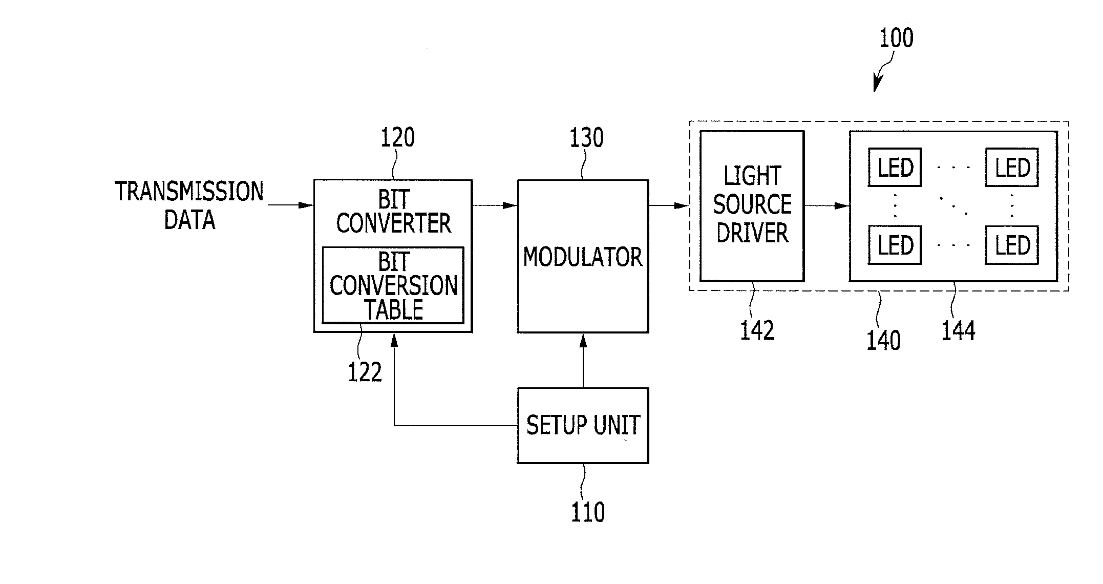
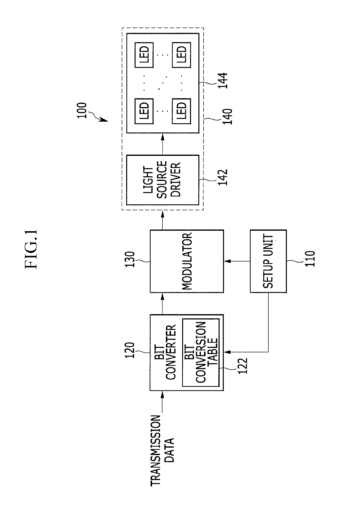
[0044]Now, a data transmitting and receiving apparatus and method for visible light communication according to an exemplary embodiment of the present invention will be described in details wi...


PUM


Abstract

An apparatus for transmitting data for visible light communication sets up the pulse width control step of pulse width modulation (PWM) in a unit time interval, modulates each symbol of VLC source data input into a PWM signal in accordance with the pulse width control step, generates a visible light modulation signal by controlling the turn-on time or turn-off time of a plurality of light emitting diodes (LEDs) in response to the PWM signal, and transmits the visible light modulation signal.

Description

CROSS-REFERENCE TO RELATED APPLICATION[0001]This application claims priority to and the benefit of Korean Patent Application No. 10-2010-0097915 and 10-2011-0061090 filed in the Korean Intellectual Property Office on Oct. 7, 2010 and Jun. 23, 2011, the entire contents of which are incorporated herein by reference.BACKGROUND OF THE INVENTION[0002](a) Field of the Invention[0003]The present invention relates to a data transmitting and receiving apparatus and method for visible light communication, and more particularly, to the data transmitting and receiving apparatus and method for visible light communication, which can minimize the brightness reduction and mitigate the flicker of a light source in visible light communication.[0004](b) Description of the Related Art[0005]Recently, as lighting apparatuses using light emitting diodes (LEDs) as light sources have spread, the visible light communication (VLC) technology for communication using LED lighting apparatuses is being introduced...

Claims


Application Information

Patent Timeline
Patent Type & Authority Applications(United States)
IPC IPC(8): H04B10/04
CPCH04B10/116
Inventor LIM, SANG-KYUJANG, IL-SOONKIM, DAE HOKIM, YON JINKANG, TAE-GYU
Owner ELECTRONICS & TELECOMM RES INST
Why Eureka
Try Eureka