Cathode ray tube

A cathode ray tube, inner surface technology, applied in the direction of cathode ray tube/electron beam tube, cathode ray/electron beam tube shell/container, discharge tube, etc. question

Inactive Publication Date: 2004-10-20
SAMSUNG SDI CO LTD
View PDF2 Cites 0 Cited by
  • Summary
  • Abstract
  • Description
  • Claims
  • Application Information

AI Technical Summary

Problems solved by technology

However, Japanese Unexamined Publication No. 10-154472 designs the inner surface of the yoke without considering the strength of the cathode ray tube against external pressure and the path trajectory of the electron beam

Method used


Image

  • Cathode ray tube
  • Cathode ray tube
  • Cathode ray tube

Examples


Embodiment Construction

[0027] Detailed description will be given with reference to preferred embodiments of the present invention and accompanying drawings.

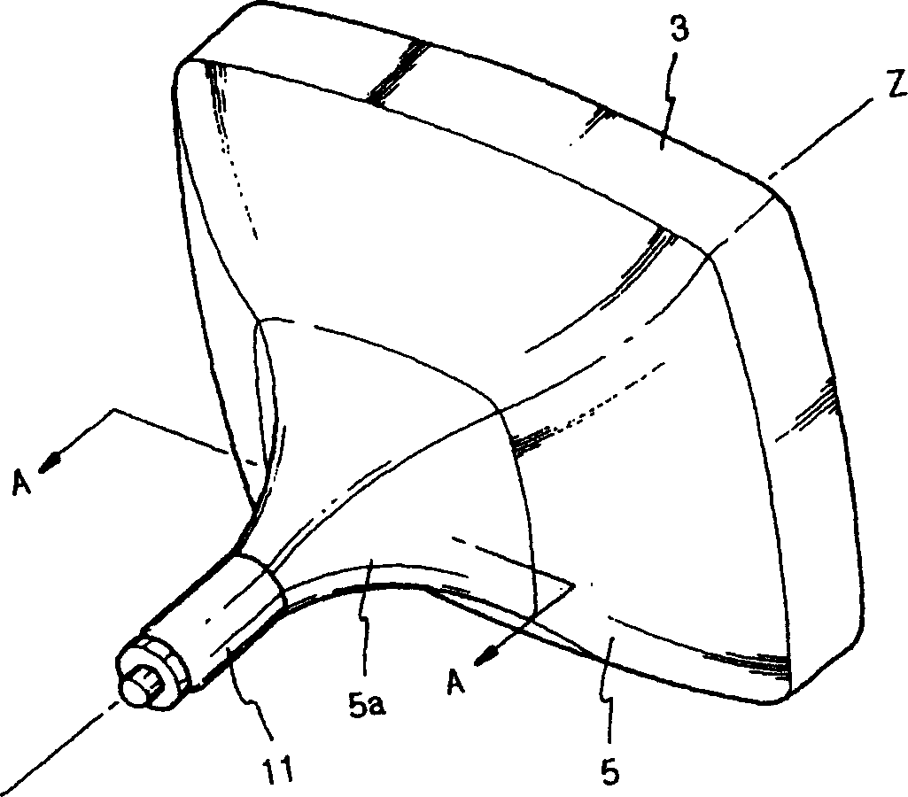
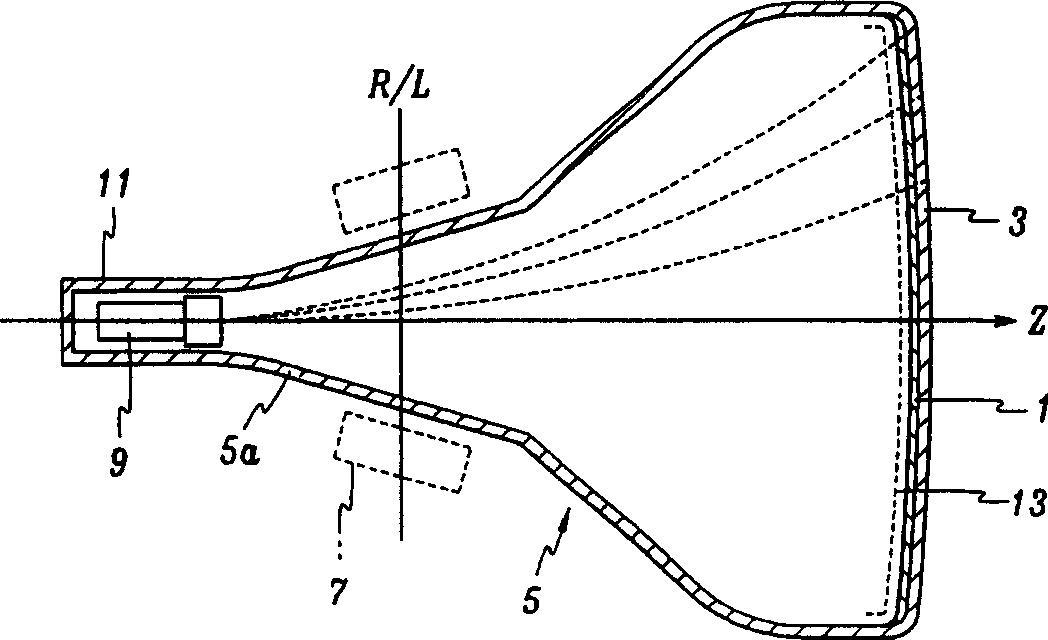
[0028] like figure 1 and 2 As shown, a cathode ray tube is formed with a substantially rectangular faceplate 3, a funnel 5 continuous adjacent to the faceplate 3, and a cylindrical neck 11 continuous with the small-diameter end portion of the funnel 5. Phosphor screen 1 is formed on the inner surface of panel 3 , and deflection yoke 7 is mounted on conical portion 5 a of funnel 5 . An electron gun assembly 9 for emitting three electron beams is arranged on the neck 11 . The three electron beams emitted by the electron gun assembly 9 are respectively deflected to the horizontal and vertical directions of the panel 3 by the horizontal and vertical deflection fields generated by the deflection yoke 7 . The deflected electron beams pass through a shadow mask 13 installed on the inner surface of the panel 3 to reach the fluorescent screen 1, an...


PUM


Abstract

A cathode ray tube includes a rectangular panel on which a phosphor screen is formed, a cylindrical neck in which an electron gun is disposed, and a funnel formed contiguous to the panel. The funnel includes a cone part whose interior surface has a circular section at the position contiguous to the neck. The circular section is deformed from the neck side to the panel side to have a non-circular section having a maximum diameter along a direction other than the horizontal and vertical axis, and distances from a funnel axis to interior surface of the cone part are non-linearly increases or decreases, and the vertical interior surface is convexed to the funnel axis with fulfilling the following condition deltaH / rd<0.16,where rd represents a distance from the funnel axis to the interior surface of the funnel at the diagonal direction, and deltaH represents a distance from a vertical line which connects the neighboring two corner points formed at the convexed interior surface to the top of the convexed interior surface.

Description

[0001] This application is a divisional application of Patent Application No. 99104832.6, filed April 8, 1999, entitled "Cathode Ray Tube". technical field [0002] The present invention relates to a cathode ray tube (CRT), and more particularly, to a cathode ray tube capable of deflecting electron beams and having enhanced strength against external stress. Background technique [0003] A CRT is a device that displays images on a screen by vertically and horizontally deflecting electron beams generated by an electron gun and landing the deflected electron beams on a screen to form a phosphor layer. The deflection of the electron beam is controlled by deflection coils mounted on the outer surface of the CRT funnel, and it forms vertical and horizontal magnetic fields. CRTs are commonly used in color televisions (TVs), monitors, and high-definition televisions (HDTVs). As the use of CRTs increases, there is a need to reduce the length of CRTs in order to increase the brightne...

Claims


Application Information

Patent Timeline
Patent Type & Authority Applications(China)
IPC IPC(8): H01J9/24H01J29/86
CPCH01J2229/8609H01J29/861H01J9/24
Inventor 朴原石金度年
Owner SAMSUNG SDI CO LTD
Why Eureka
Try Eureka