Pseudo-random squence generator and associated method

A pseudo-random sequence and generator technology, used in random number generators, instruments, digital transmission systems, etc., can solve a large number of problems such as operations

Inactive Publication Date: 2004-10-27
TELEFON AB LM ERICSSON (PUBL)
View PDF0 Cites 1 Cited by
  • Summary
  • Abstract
  • Description
  • Claims
  • Application Information

AI Technical Summary

Problems solved by technology

But such a map require

Method used


Image

  • Pseudo-random squence generator and associated method
  • Pseudo-random squence generator and associated method
  • Pseudo-random squence generator and associated method

Examples


Embodiment Construction

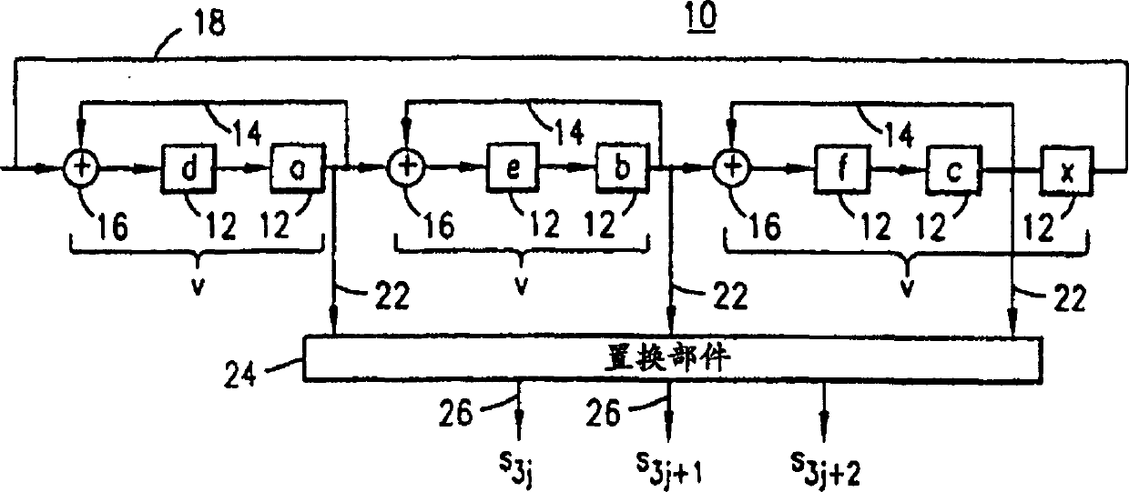
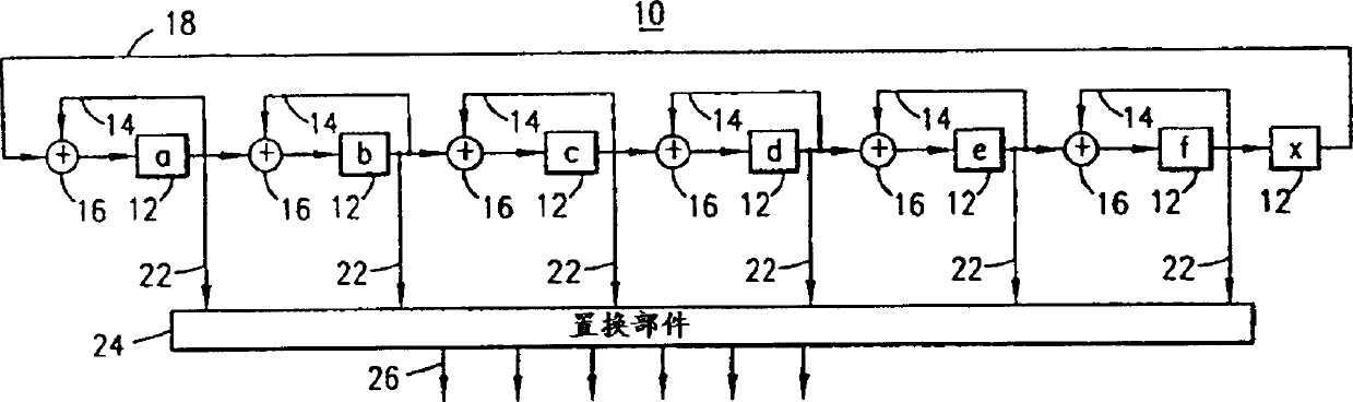
[0057] Referring first to FIG. 1 , an exemplary windmill generator, indicated generally at 10 , is shown consisting of a plurality of time delay elements 12 divided into v blade groups. Here, the blade length L of each blade i , each blade v includes a feedback loop 14 connected to the input of the summing unit 16 . The rightmost (shown as vane v) is further connected in a feedback loop 18 to the leftmost vane v.

[0058] A tap 22 is taken from each blade v and provided to a permutation unit which performs a permutation, where an identical permutation is performed according to the sequence provided by the taps 22 . The output sequence formed by permutation component 24 composes the output terminal tuple produced on line 26, here denoted by S 3j , S 3j+1 , S 3j+2 ,express.

[0059] The length L of each blade v is denoted as L i , where i=0, 1, . . . , v-1. lengthL o to L v-1 The group of is determined by a known formula. When L=L 0 +L 1 +... L v-1 It has special si...


PUM


Abstract

A method, and associated apparatus, for generating a pseudo-random number sequence. Determinations are made of compatible configurations of windmill generators for a selected windmill polynomial. Implementation of a windmill generator is made through use of word-oriented memory elements. Words stored in the memory elements are selectively outputted to form portions of a pseudo-random number sequence.

Description

technical field [0001] The present invention generally relates to the generation of pseudo-random number sequences used, for example, in encryption processes. More specifically, the present invention relates to pseudorandom number sequence generators and related methods for generating pseudorandom number sequences corresponding to sequences generated using selected Windmill polynomials. The invention further relates to a way for determining compatibility between different configurations of pinwheel polynomial based pseudo-random sequence generators. [0002] Word-oriented storage elements are used to store the words that make up the sequence of pseudo-random numbers. The size of the memory word is chosen such that the size of the sequence portion produced by the windmill generator during successive iterations of operation can easily be increased, if desired, in order to generate the same pseudorandom sequence of numbers, corresponding to selectable compatible pinwheel genera...

Claims


Application Information

Patent Timeline
IPC IPC(8): G06F7/58G09C1/00H04L9/22
CPCH04L9/0662H04L2209/12Y04S40/20
Inventor B·J·M·斯梅茨
Owner TELEFON AB LM ERICSSON (PUBL)
Why Eureka
Try Eureka