
Self-tightening type drill chuck in modified structure

An improved structure and drill chuck technology, which is applied in the mechanical field, can solve problems such as complex structure and insufficient reliability, and achieve the effect of loosening and labor saving, simple and reasonable structure, and high reliability

Inactive Publication Date: 2005-01-12
游友民
View PDF0 Cites 10 Cited by
  • Summary
  • Abstract
  • Description
  • Claims
  • Application Information

AI Technical Summary

Problems solved by technology

However, the self-tightening drill chuck also has disadvantages suc

Method used


Image

  • Self-tightening type drill chuck in modified structure
  • Self-tightening type drill chuck in modified structure
  • Self-tightening type drill chuck in modified structure

Examples


Embodiment Construction

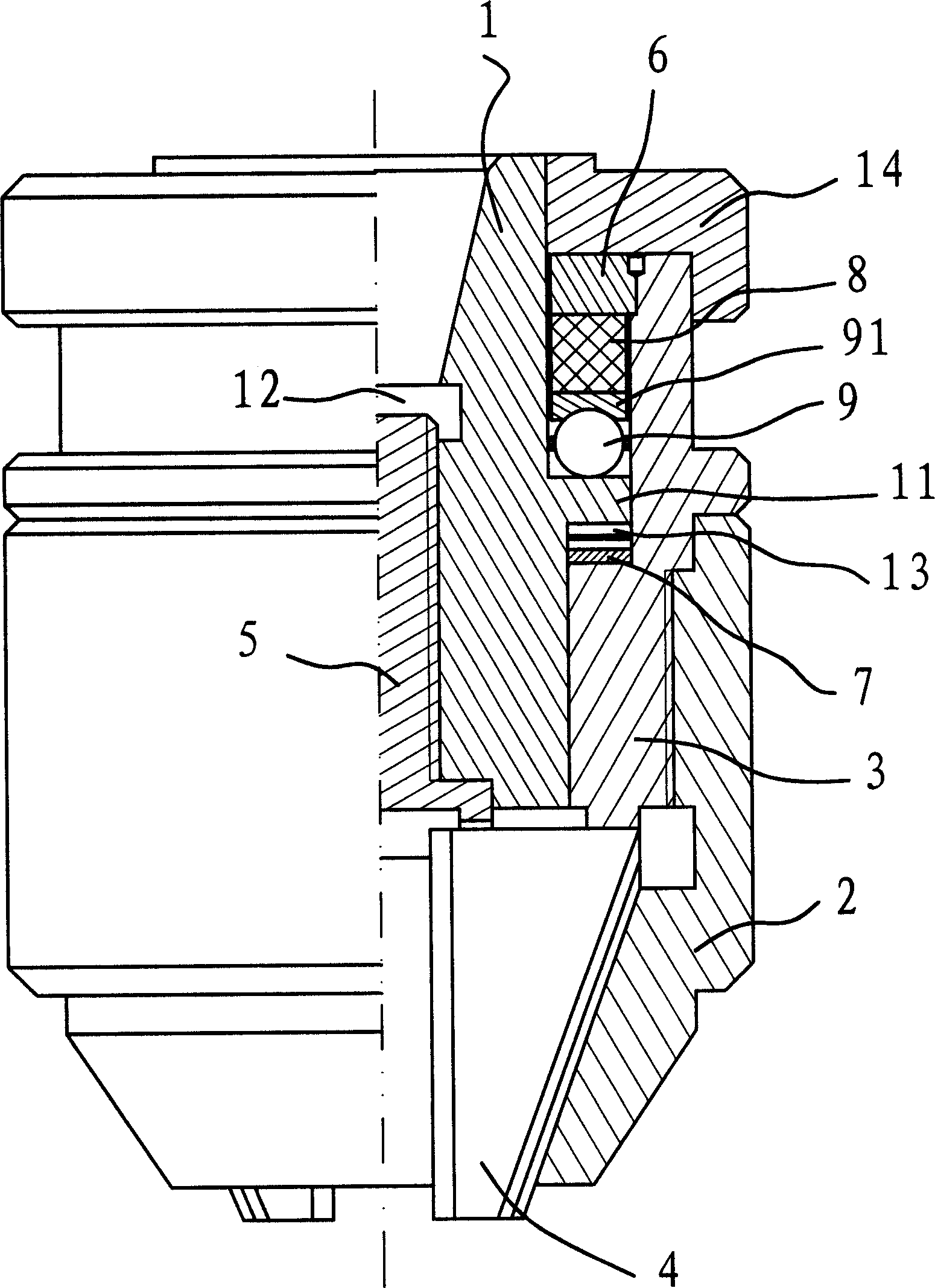
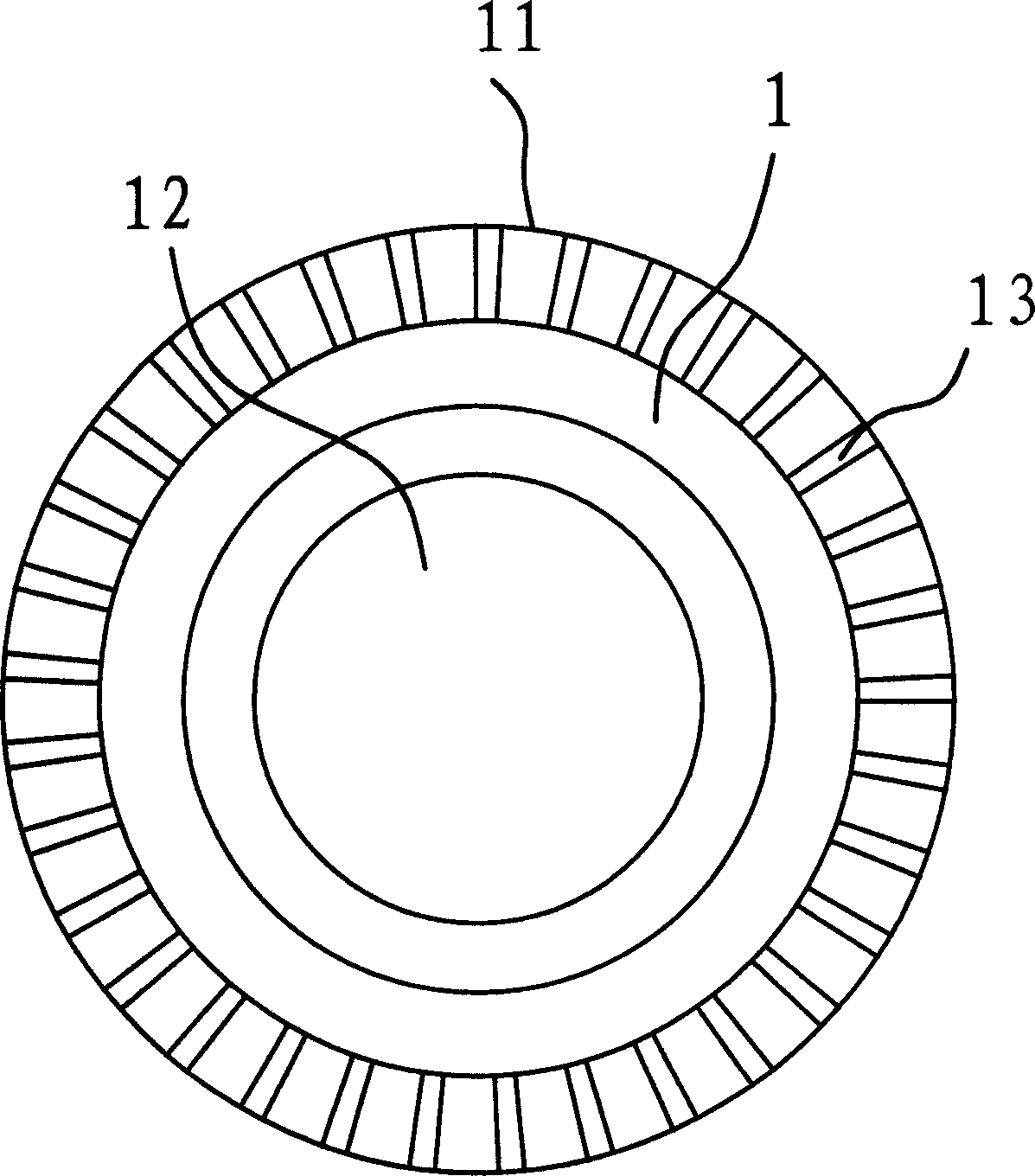
[0018] Such as figure 1 As shown, the self-tightening drill chuck of the improved structure includes the main body of the drill chuck 1, the ball cover 6, the clamping jaw seat 3, the self-tightening screw 5, the clamping jaw 4, the outer cover 2 and other parts. The main body 1 has an approximately cylindrical structure with a through hole 12 in the center, and the self-tightening screw 5 is connected with the main body 1 through threads. In the process of rotating the main body 1, if the self-tightening screw 5 does not rotate, it will stretch up and down along the main body 1.

[0019] The clamping jaw seat 3 is sleeved outside the main body 1. There is a ball cover 6 on the upper part of the jaw seat 3. The ball cover 6 is fixed on the inner side of the jaw seat 3. The ball cover 6 restricts the main body 1 in the jaw seat 3. The outer casing 2 is connected with the clamping jaw base 3 through threads.

[0020] Like the ordinary drill chuck, there are three guide grooves on t...


PUM


Abstract

A self-clinching fixture with improved structure for drill bit is composed of a main body with a lateral shoulder, a rolling ball cover, the bearing and elastomer between said shoulder and cover, jaw holder, jaws installed in said jaw holder, external jacket, self-fastening screw liked to main body via spiral threads, an elastic plate under said shoulder and having several elastic pieces with boss, and a unidirectional ratchet on the lateral lower surface of said shoulder.

Description

Technical field [0001] The invention belongs to the technical field of machinery, and particularly relates to a drill chuck used on a machine tool or a drilling machine. Background technique [0002] On bench drills, hand electric drills or machine tools used in machinery manufacturing, electronics, textiles, medicine and other industries, it is often necessary to use drill chucks to hold drilling tools or knives. The existing drill chucks usually have two types: one is a wrench drill chuck, which requires auxiliary tools when clamping and loosening the drill bit, which is troublesome to operate; the other is a self-tightening drill chuck. Chuck. The self-tightening drill chuck uses the principle of self-tightening, which makes it easy to clamp the drill bit. However, it is often difficult to loosen and unload the drill due to excessive clamping force. [0003] To this end, many people are studying this problem and have proposed various solutions, and some hav...

Claims


Application Information

Patent Timeline
IPC IPC(8): B23B31/12B23B51/12B23Q3/12
Inventor 游友民
Owner 游友民
Features
  • Generate Ideas
  • Intellectual Property
  • Life Sciences
  • Materials
  • Tech Scout
  • Unparalleled Data Quality
  • Higher Quality Content
  • 60% Fewer Hallucinations
Learn More