Embedded sign light device

A technology for identifying lamps and lamp bodies, which is applied in lighting devices, electric lamp circuit layout, fixed lighting devices, etc., can solve problems such as difficulty in abnormality, and achieve a good surge voltage effect

Inactive Publication Date: 2005-02-09
TOSHIBA LIGHTING & TECH CORP
View PDF1 Cites 5 Cited by
  • Summary
  • Abstract
  • Description
  • Claims
  • Application Information

AI Technical Summary

Problems solved by technology

Since the halogen bulb used as a conventional light source in the embedded marker light device is used alone, it is possible to perform the above-mentioned operation without any problem by connecting the thin film cutout and the light source in parallel in advance.
However, in the case where the light source of the recessed marker light device is composed of several light emitting diodes that are turned on at the same time, even if some light emitting diodes are turned off due to malfunction, the remaining light emitting diodes still keep on. Visually, it is difficult to accurately determine whether there is an abnormality

Method used


Image

  • Embedded sign light device
  • Embedded sign light device
  • Embedded sign light device

Examples


Embodiment Construction

[0094] Embodiments of the present invention will be described below with reference to the drawings.

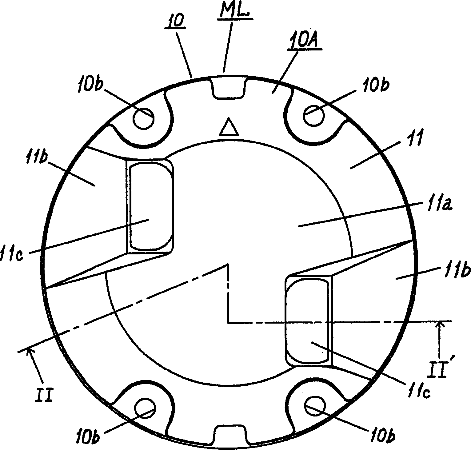
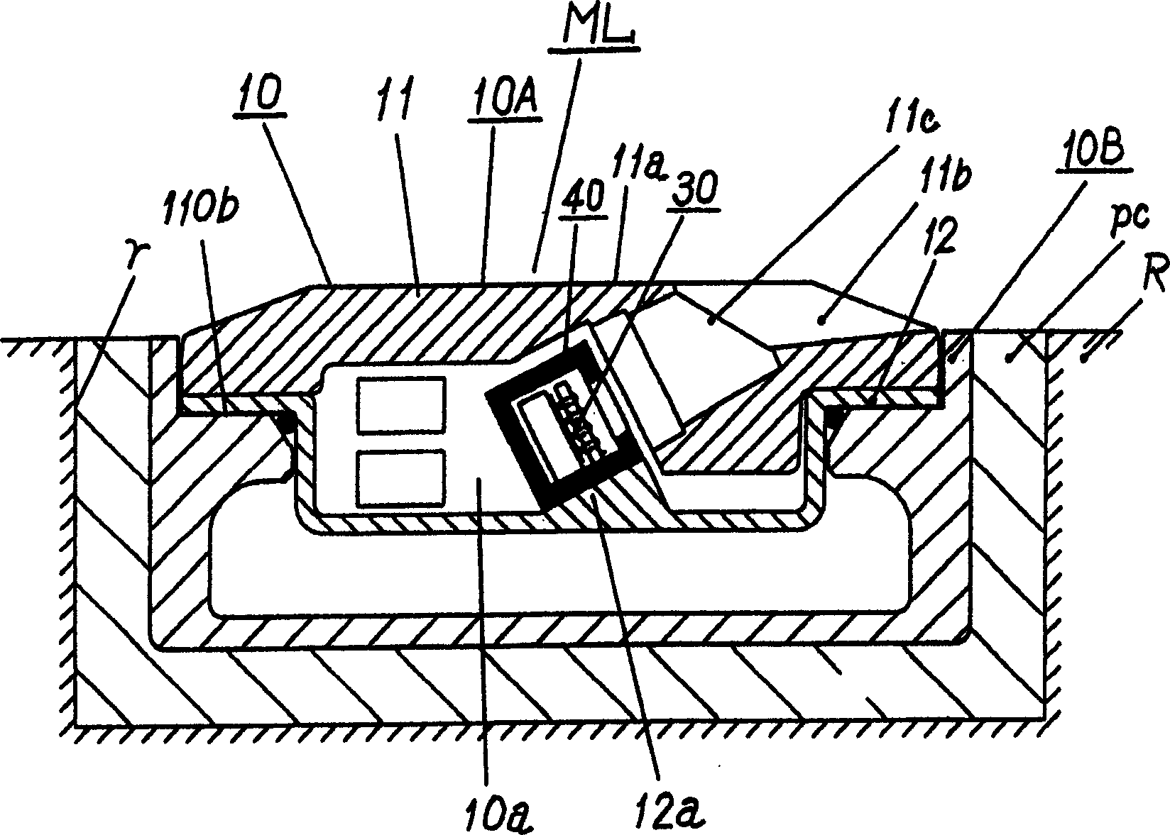
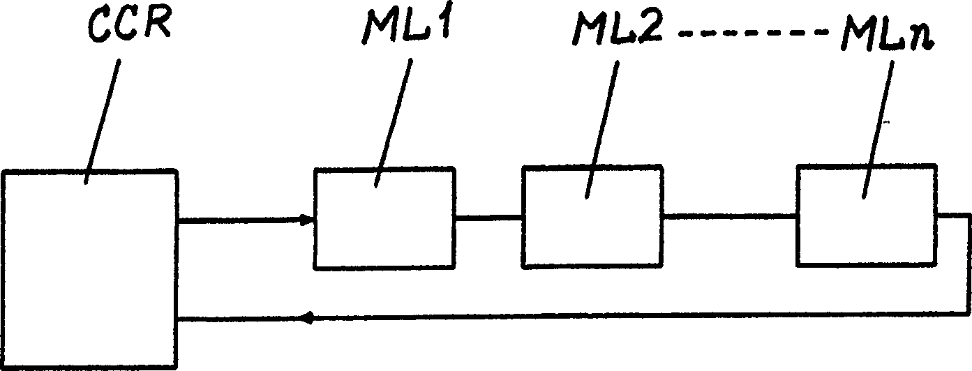
[0095] Figure 1 to Figure 6 Shown is a built-in marker light device for an airport as a first embodiment of the built-in marker light device of the present invention, figure 1 for the floor plan, figure 2 for along figure 1 The enlarged cross-sectional view of the line II-II', image 3 It is a circuit block diagram for explaining the series lighting method of several embedded marker light devices for airports, Figure 4 It is an enlarged cross-sectional view of the light source and heat insulation components, Figure 5 It is the circuit diagram of the light-emitting diode lighting circuit and the surge absorbing circuit, Figure 6 It is the circuit block diagram of the light source monitoring control circuit. In this embodiment, the embedded marker light ML for airports is composed of a marker light main body 10 , an input terminal 20 , a light source 30 , a heat insul...


PUM


Abstract

PROBLEM TO BE SOLVED: To provide an embedded beacon light device suitable especially for an airport, with operational problems (surge voltage, operation temperature of light-emitting diodes, and partial light out of a plurality of light-emitting diodes) solved on a light source consisting of the plurality of light-emitting diodes. ŽSOLUTION: The embedded beacon light device ML is provided with a beacon light main body 10 provided with a metal light body 10A and buried in a roadbed, an input terminal 20 arranged at the beacon light main body 10, a light source consisting of the plurality of light-emitting diodes 31 arranged at the metal light body 10A of the beacon light main body 10 to be connected to the input terminal 20, and a surge absorption circuit 50 arranged at the metal light body 10A so as to absorb surge entering from the input terminal 20 and with its grounding terminal connected to the metal light body 10A. A plurality of the light bodies are connected in series with a constant-current alternate-current power source CCR. Ž

Description

technical field [0001] The present invention relates to an embedded marking light device which uses light-emitting diodes as a light source, embeds several of them in the roadbed at intervals, and is connected in series with a constant current AC power supply, and is suitable for use in airports and the like. Background technique [0002] In embedded marker lights used in airports and the like, there is known a technology of long-life light emitting diodes instead of conventionally used light sources such as halogen bulbs (for example, refer to Patent Document 1). As a result, maintenance costs for light source replacement can be significantly reduced. [0003] [Patent Document 1]: [0004] Japanese Patent Laying-Open No. Hei 9-269746, which is an early publication of Japanese patents. [0005] However, such embedded marker light devices are installed at relatively large intervals in a state of being buried in the roadbed, and most of them are supplied and used in a specia...

Claims


Application Information

Patent Timeline
Patent Type & Authority Applications(China)
IPC IPC(8): B64D47/02E01F9/576E01F9/582F21S2/00F21W111/02F21W111/06H01L33/00H05B37/02H05B37/03
CPCF21W2111/06F21S8/022F21Y2101/02F21Y2115/10
Inventor 井手胜幸长谷川润治石田康史村田淳哉新野真吾百海周
Owner TOSHIBA LIGHTING & TECH CORP
Why Eureka
Try Eureka