Image pickup apparatus

A technology of a camera device and a camera tube, which is applied in the directions of image communication, television, and record carrier structural parts, etc., can solve the problems of occupying a large space, interfering with the opening of the disk cover, and difficult to load the disk-shaped recording medium, so as to prevent accidents. fall effect

Inactive Publication Date: 2005-06-22
SONY CORP
View PDF4 Cites 3 Cited by
  • Summary
  • Abstract
  • Description
  • Claims
  • Application Information

AI Technical Summary

Problems solved by technology

[0019] The problem to be solved is that since the disc-shaped recording medium is standardized in many aspects (such as size and thickness), it is difficult to make the entire imaging device miniaturization
Also, in a small-sized camera unit, depending on the opening direction of the cover, the belt pull interferes with the opening of the disk cover
Therefore, it is difficult to load and eject the disc-shaped recording medium in the small-sized imaging device.
[0020] Also, when the disk cover installed on the casing so as to be freely opened and closed is arranged on the cover opening and closing mechanism, because the disk cover is will be kept closed, therefore, the cover opening and closing mechanism of the related art takes up a large space, so it is difficult to make the entire imaging device smaller in size and thinner in thickness
[0021] Also, when the upper portion of the accessory shoe protrudes in the upward direction from the upper surface of the camera body, the imaging device is complicated from a design point of view due to the protruding portion of the accessory shoe, and the protruding portion of the accessory shoe necessarily Interfere with the operation of the camera

Method used


Image

  • Image pickup apparatus
  • Image pickup apparatus
  • Image pickup apparatus

Examples


Embodiment 1

[0116] The present invention will be described below with reference to the accompanying drawings.

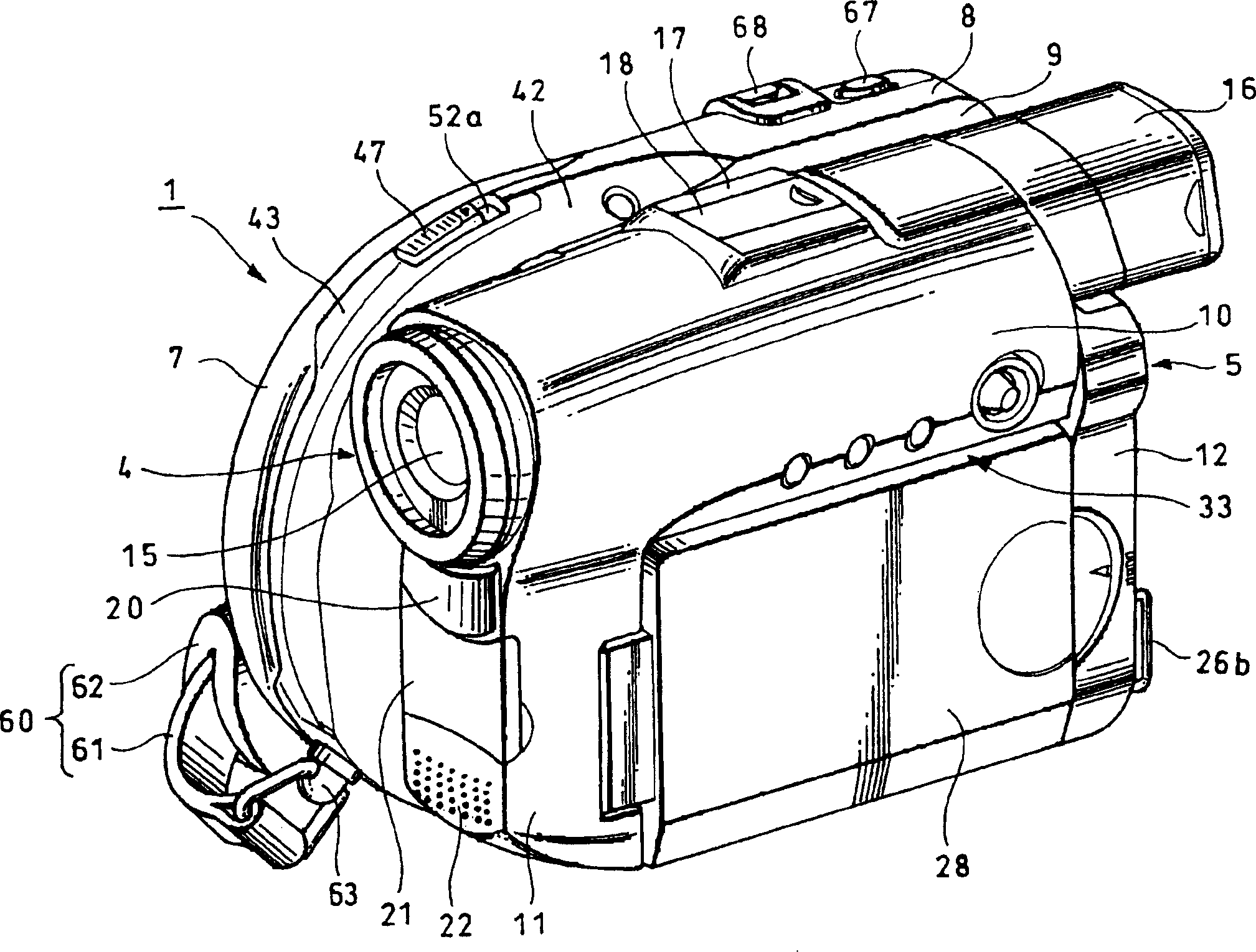
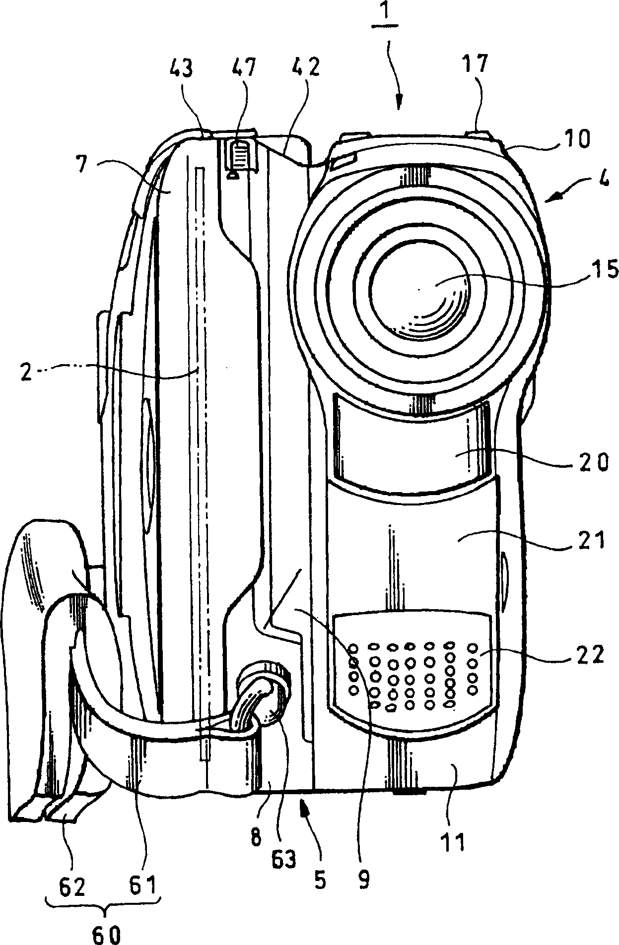
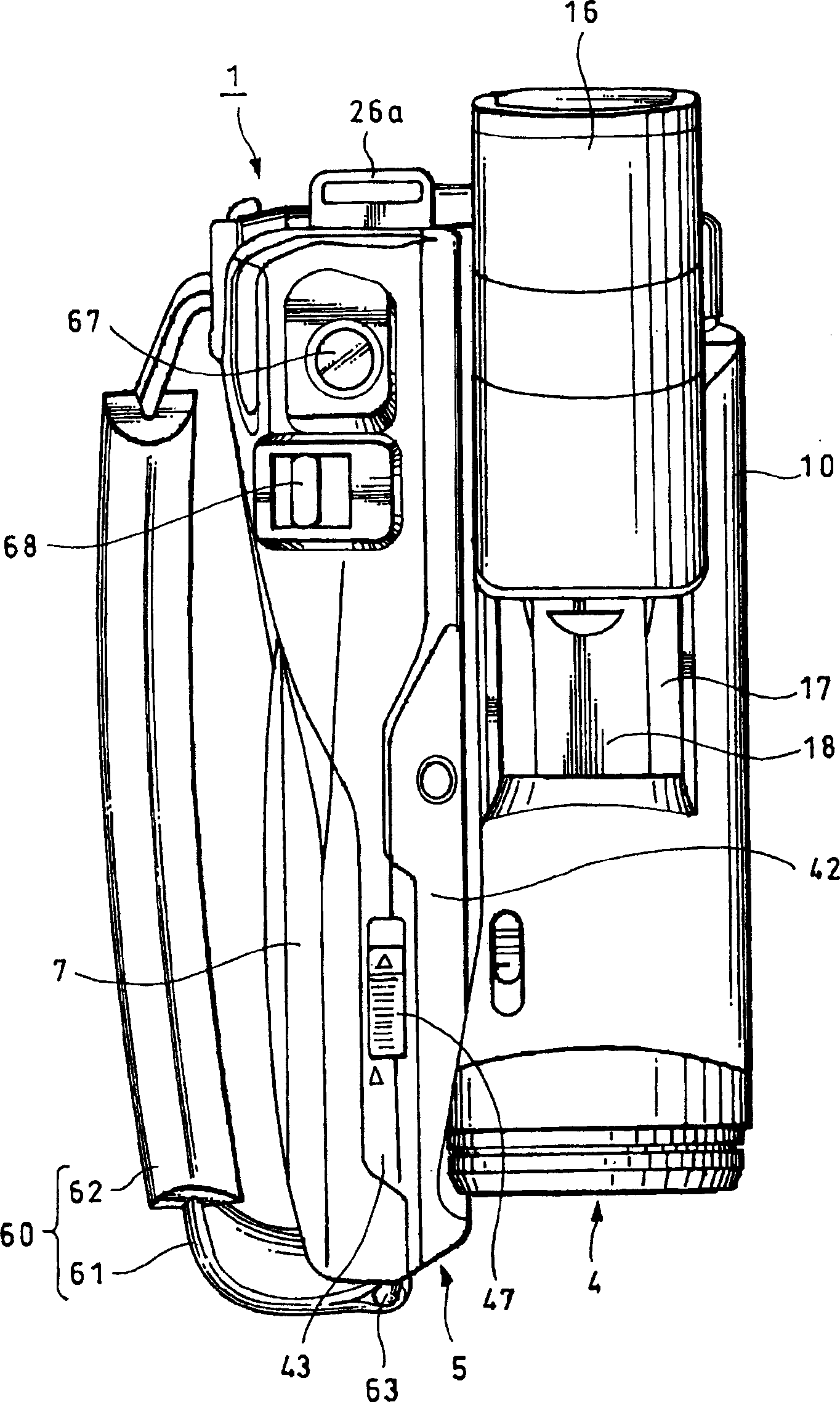
[0117] Figures 1 to 4 3 represents an imaging device according to an embodiment of the present invention. more specifically, Figures 1 to 4 Respectively, a perspective view, a front view, a plan view and a side view of an imaging device representing an embodiment of the present invention; Figure 5 is a rear perspective view showing the camera device with its display device open; Image 6 is a perspective view showing the imaging device viewed from the rear side of the magnetic disk; Figure 7 is a front perspective view showing the camera device with its disk cover open; Figure 8 is a perspective view showing an imaging device on which a disc-shaped recording medium is mounted; Figure 9 is a side view of the imaging device of the present invention; Figure 10 is an explanatory diagram showing a state when a user holds the imaging device with a hand when using the imag...


PUM

PropertyMeasurementUnit
diameteraaaaaaaaaa

Abstract

In a small-sized imaging device, depending on the opening direction of the cover, a belt pull or the like becomes an obstacle, and it is difficult to open the disk cover at a large angle. Therefore, the disk-shaped recording medium cannot be mounted on and detached from the disk-type image pickup device without difficulty. Comprise in the disk-type imaging device: platen rotating device 35, be used to make turntable 36 rotate, DVD2 is detachably installed on turntable 36 with upright state; The information signal of the image corresponding to the object light is recorded on the DVD2 rotated by the platen rotating device 35; the housing 5 includes a disk compartment part 6 for accommodating the platen rotating device 35 and the optical pickup tube device 71, opening to the side surface The platen is located in the disk compartment part; the disk cover is installed on the casing 5 so as to be freely opened and closed to cover the disk compartment part 6. A cover rotation shaft portion 39 is arranged at the rear of the side surface of the casing 5 to rotatably support the disk cover 7 which is rotatable in the lateral direction about the cover rotation shaft portion 39 .

Description

technical field [0001] The present invention relates to an imaging device capable of recording information signals on and / or reproducing information signals from a disc-shaped recording medium detachably mounted on the imaging device; An imaging device, wherein a disk cover mounted on a case can be opened forward, so that the disk cover can be opened laterally. [0002] Also, the present invention relates to an imaging device in which the cover opening and closing mechanism of the disk cover is arranged near a vacant area near the disk drive device inside the casing, so that the device can be made smaller in size and reduced in thickness. [0003] Furthermore, the present invention relates to an imaging device in which the risk of an accessory shoe arranged at an upper portion of a casing being caught by an object is eliminated by eliminating or reducing the amount of protrusion of the accessory shoe on an upper surface; It also relates to an imaging device capable of miniatu...

Claims


Application Information

Patent Timeline
Patent Type & Authority Applications(China)
IPC IPC(8): H04N5/225G11B17/04G11B25/04G11B31/00G11B33/02H04N5/247H04N5/76
CPCG11B31/006H04N23/00
Inventor 井泽秀俊新井静夫土屋务堤裕加
Owner SONY CORP
Why Eureka
Try Eureka