Adhesive tape sweeping structure

A tape cleaning and belt technology, which is applied in the direction of cleaning devices, transportation and packaging, and conveyor objects, can solve the problems of up and down vibration, that is, up and down movement, increase the rotating workload of the transmission roller, and reduce the effective transmission volume, etc., to achieve Increase practicality, enhance the scope of application, and reduce the effect of difficulty

Active Publication Date: 2014-08-06
CHENGDU HAILINGDA MACHINERY
View PDF5 Cites 3 Cited by
  • Summary
  • Abstract
  • Description
  • Claims
  • Application Information

AI Technical Summary

Problems solved by technology

[0004] In the long-term working state of the belt conveyor, more material residues will accumulate on the transmission surface of the belt, and the residual materials will adhere to the transmission surface and rotate with the belt, which greatly increases the workload of the transmission roller when it rotates. And the residual material will generally not slide down to the destination together with the material, while reducing the effective conveying capacity, it will also cause a certain degree of damage to the belt; at present, when cleaning the residual material on the surface of the belt, more Alloy

Method used


Image

  • Adhesive tape sweeping structure
  • Adhesive tape sweeping structure
  • Adhesive tape sweeping structure

Examples


Embodiment 1

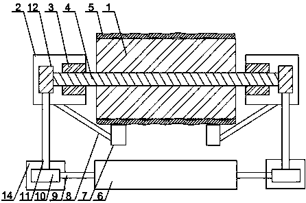
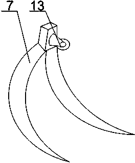
[0025] Such as Figure 1 to Figure 4As shown, the adhesive tape cleaning structure of the present invention includes a transmission drum 1 and a support cylinder 2, a bearing seat 3 is installed in the support cylinder 2, and a rotating shaft 4 of the transmission cylinder 1 runs through one end of the support cylinder 2 and is rotatably arranged in the bearing housing 3 , the rotating shaft 4 is provided with a knife loading shaft 6 parallel to the rotating shaft 4, the knife loading shaft 6 is installed at the position before the belt 5 turns, and a plurality of blades 15 are arranged on the knife loading shaft 9 A plurality of said blades 15 are hinged with the cutter shaft 9 and the annular array is distributed on the outer wall of the cutter shaft 9, the cutter shaft 9 is placed in the fixed cylinder 6 and the two ends of the cutter shaft 9 protrude from both ends of the fixed cylinder 6 At the end, there is an opening corresponding to the blade 15 on the fixed cylinder 6...

Embodiment 2

[0027] Such as figure 1 As shown, this embodiment is based on Embodiment 1. The blade adjustment structure includes a screw 17 and an arc-shaped plate 16. The arc-shaped plate 16 is connected to the inner side of the blade 15, and an internal thread hole 18 is opened on the arc-shaped plate 16. , the screw rod 17 is rotatably arranged at the end of the fixed cylinder 6, and the screw rod 17 passes through the inner threaded hole 18 and is threadedly engaged with the arc-shaped plate 16. Blade 15 of the present invention adopts arc blade, and according to the thickness size of the residual material on belt 5, under the condition of not moving cutter shaft 9, the opening angle of blade 15 is increased, to reduce the gap between blade 15 and residual material. Adjust the distance between the screw rods 17 so that the arc-shaped plate 16 moves quickly through the screw rod 17 and the internal threaded hole 18, and then drives the blade 15 to move to realize the adjustment of the b...

Embodiment 3

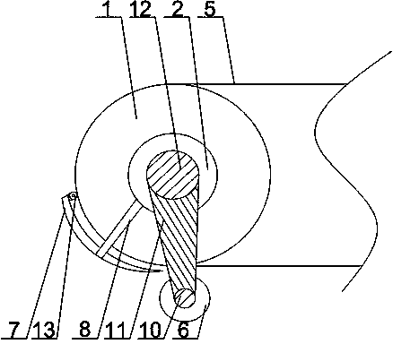
[0029] Such as Figure 1 to Figure 3 As shown, in this embodiment, on the basis of Embodiment 1, a large gear 12 is installed at both ends of the rotating shaft 4, and a protection cylinder 14 is installed at both ends of the fixed cylinder 6, and a small gear 10 is arranged in the protection cylinder 14. , the end of the cutter shaft 9 runs through one side of the protective tube 14 and is connected with the pinion 10 , the two ends of the connecting rod 11 are equipped with racks, and the bull gear 12 cooperates with the pinion 10 through the connecting rod 11 . The rotating shaft 4 rotates, and under the cooperation of the large gear 12, the small gear 10 and the connecting rod 11, the rotating shaft 4 will drive the knife loading shaft 6 and the transmission roller 1 to rotate synchronously, so as to ensure that the knife loading shaft 6 is in contact with the residual material and cleaned up .


PUM

PropertyMeasurementUnit
Angleaaaaaaaaaa

Abstract

The invention discloses an adhesive tape sweeping structure which comprises a transmitting roller and a supporting drum. A knife installing shaft parallel to a rotating shaft is rotatably arranged on the rotating shaft, installed at the position of a belt rotating forwards and provided with a plurality of blades. The knife installing shaft is placed in a fixed drum, two ends of the knife installing shaft are protruded out of two ends of the fixed drum, the fixed drum is provided with an opening corresponding to the blades, the blades penetrate the opening, and blade adjusting structures are further installed between every two adjacent blades. A V-shaped blade is fixed on the supporting drum through a connecting rod and is in an arc shape matched with the outer surface of the transmitting roller, and a rolling wheel is installed on a crossed part of the V-shaped blade and is in contact with a belt on the transmitting roller in work. When faults occur in the transmitting roller, so that the belt is vibrated up and down, the rolling wheel installed on the crossed part of the V-shaped blade is in contact with the belt, the V-shaped blade can be effectively protected from damage caused by transition contact between the V-shaped blade and the conveying surface of the belt, and the service life of the belt is prolonged.

Description

technical field [0001] The invention relates to a belt cleaning device, in particular to a belt cleaning structure. Background technique [0002] The belt conveyor is a friction-driven machine that transports materials in a continuous manner. It can form a material conveying process on a certain conveying line from the initial feeding point to the final unloading point. It can not only transport broken materials, but also transport finished items; in addition to pure material transport, it can also cooperate with the requirements of the technological process in the production process of various industrial enterprises to form a rhythmic flow operation transport line. [0003] Belt conveyor is also called belt conveyor. The conveyor belt moves according to the principle of friction transmission. It is suitable for conveying powdery, granular and small pieces of low-grinding materials with a bulk density of less than 1.67 / ton / m3 and easy to dig out. Bagged materials, such as ...

Claims


Application Information

Patent Timeline
IPC IPC(8): B65G45/12B65G45/14
Inventor 陈志强
Owner CHENGDU HAILINGDA MACHINERY
Why Eureka
Try Eureka