Dust separator of vacuum cleaner

A dust separation and vacuum cleaner technology, applied in suction filters and other directions, can solve the problems of heavy separation burden on downstream separators, poor cyclone separation effect, and large airflow flow, so as to improve the cyclone separation effect, reduce airflow, and improve dust filtering efficiency. Effect

Inactive Publication Date: 2006-03-22
卞庄
View PDF0 Cites 3 Cited by
  • Summary
  • Abstract
  • Description
  • Claims
  • Application Information

AI Technical Summary

Benefits of technology

This new design improves the performance of an up-cyclonic separating apparatus for removing fine particles such as dirt or debris effectively without causing damage to other components within it's structure. It also allows some of this filtered material (the filters) to return back towards their original position when they become clogged due to heavy use over time. Overall, these improvements enhances the overall functioning of the equipment while reducing downtime caused by maintenance operations.

Problems solved by technology

This patented technical problem addressed by this patents relates to improving the performance of an up-righted cleaning machine's filter system due to its lack of efficient separating devices for small particles such as dirt or debris from larger ones like sandwiches during operation.

Method used


Image

  • Dust separator of vacuum cleaner
  • Dust separator of vacuum cleaner
  • Dust separator of vacuum cleaner

Examples


Embodiment Construction

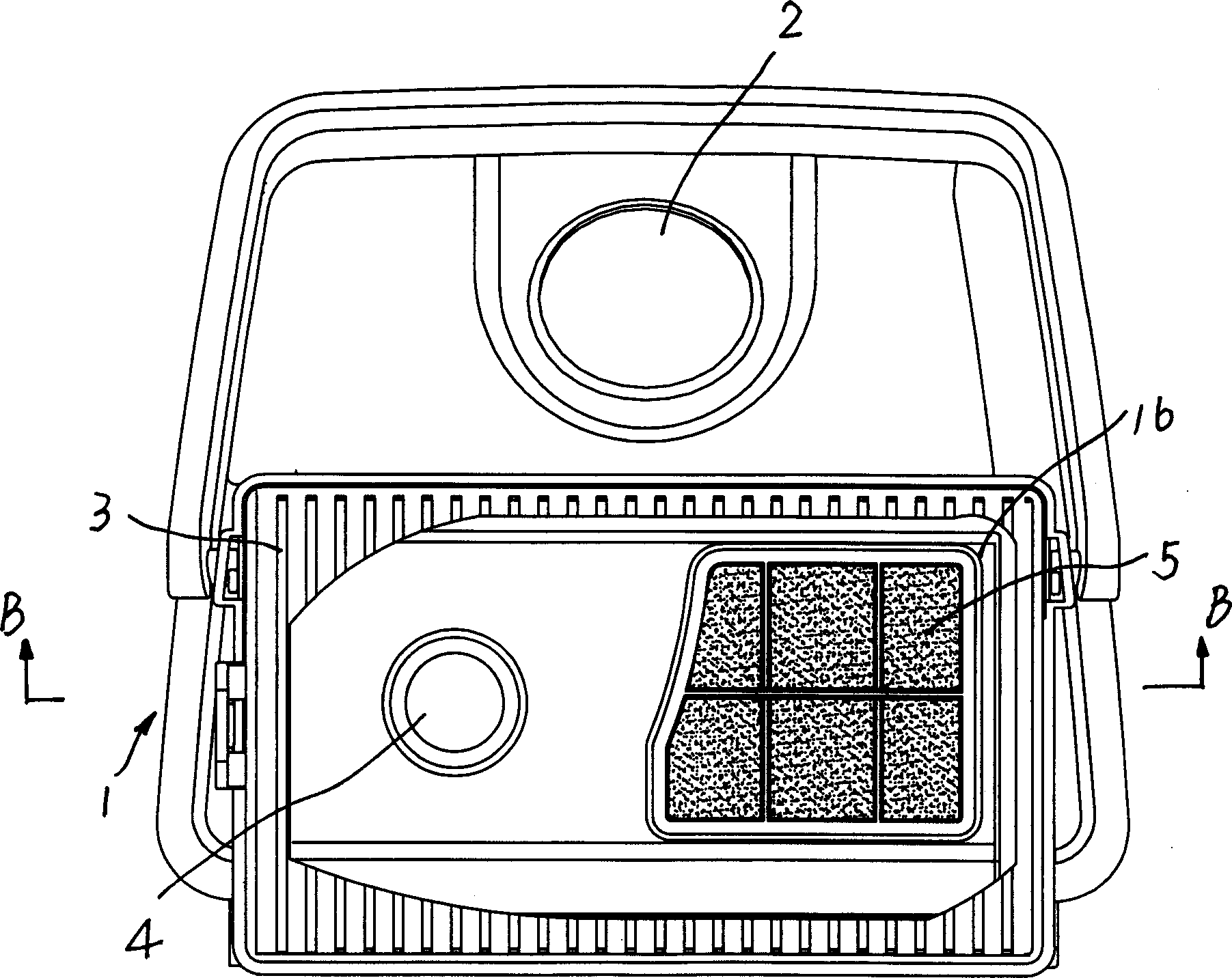
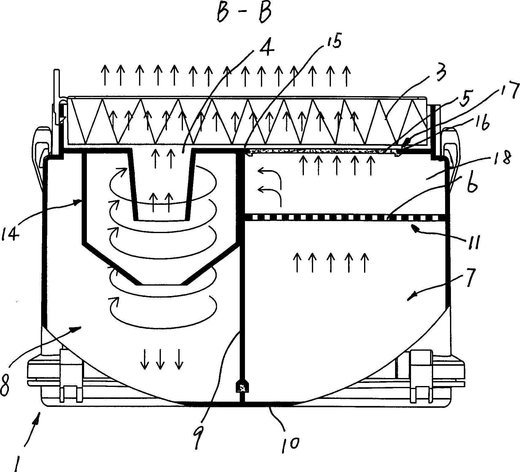
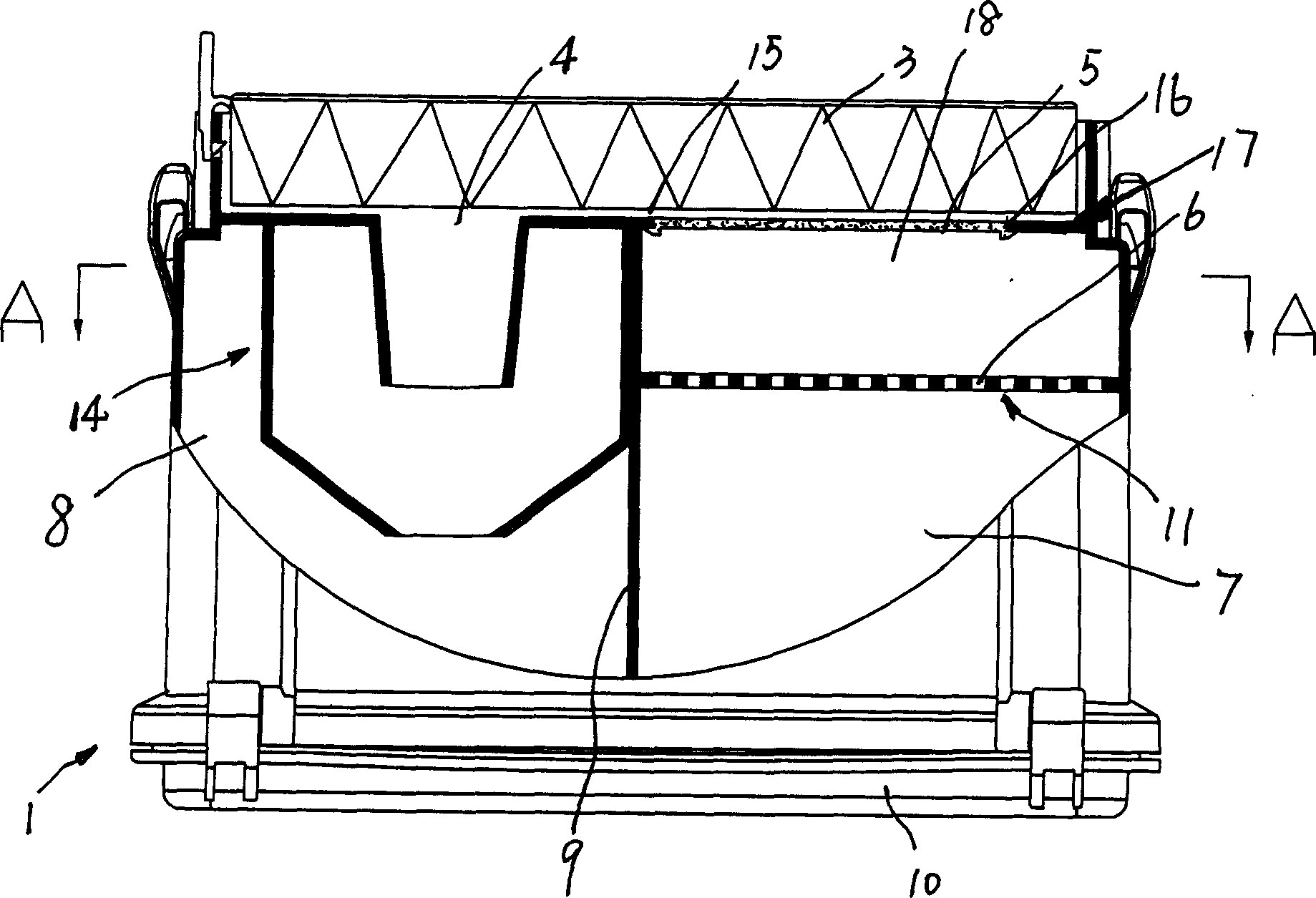
[0014] See attached figure 1 - attached Figure 5 , a dust separation device on a vacuum cleaner, which includes a first separator 17, a cyclone separator 14 located on the side of the first separator 17, and the first separator 17 includes an upstream dust chamber 7 and an air flow The distribution chamber 18, the upstream dust chamber 7 and the airflow distribution chamber 18 are separated by a mesh plate 11 with a plurality of mesh holes 6, the upstream dust chamber 7 has a dust wind inlet 2, and the The airflow distribution chamber 18 has a first airflow outlet 13 and a second airflow outlet 16, the second airflow outlet 16 is provided with a first filter 5, and the cyclone separator 14 has a cyclone inlet 12 and a cyclone outlet 4. The first air outlet 13 communicates with the cyclone inlet 12 , and the second air outlet 16 and the cyclone outlet 4 directly lead to the air outlet channel 15 .

[0015] The second filter 3 is arranged on the air outlet channel 15 .

[00...


PUM


Abstract

The dust separator of vacuum cleaner includes the first separator, and one cyclonic separator. The first separator includes one upstream dust chamber with dusty wind inlet and one airflow distributing chamber with the first airflow outlet, the second airflow outlet and the first filter in the second airflow outlet. The cyclonic separator has one cyclone inlet communicated with the first airflow outlet and one cyclone outlet. Partial airflow after separating large grain dust in the first separator flows out directly from the second airflow outlet, and this reduces the quality of airflow entering the cyclonic separator, raises the cyclonic separating effect and increases the airflow quality of the whole separator.

Description


Claims


Application Information

Patent Timeline
Owner 卞庄
Why Eureka
Try Eureka