Adaptive antenna reception method and device

An adaptive antenna and receiving method technology, applied in antenna, diversity/multi-antenna system, polarization/direction diversity, etc., can solve problems such as signal interference, and achieve the effects of avoiding misalignment and improving follow-up performance

Inactive Publication Date: 2006-07-12
NEC CORP
View PDF3 Cites 5 Cited by
  • Summary
  • Abstract
  • Description
  • Claims
  • Application Information

AI Technical Summary

Problems solved by technology

[0003] However, there is a problem in the CDMA system that when a base station receives a desired signal from a specific user, it interferes with other signals from users who simultaneously access the same base station as the specific user

Method used


Image

  • Adaptive antenna reception method and device
  • Adaptive antenna reception method and device
  • Adaptive antenna reception method and device

Examples


Embodiment Construction

[0098] Referring now to the accompanying drawings, preferred embodiments of the present invention will be described in detail.

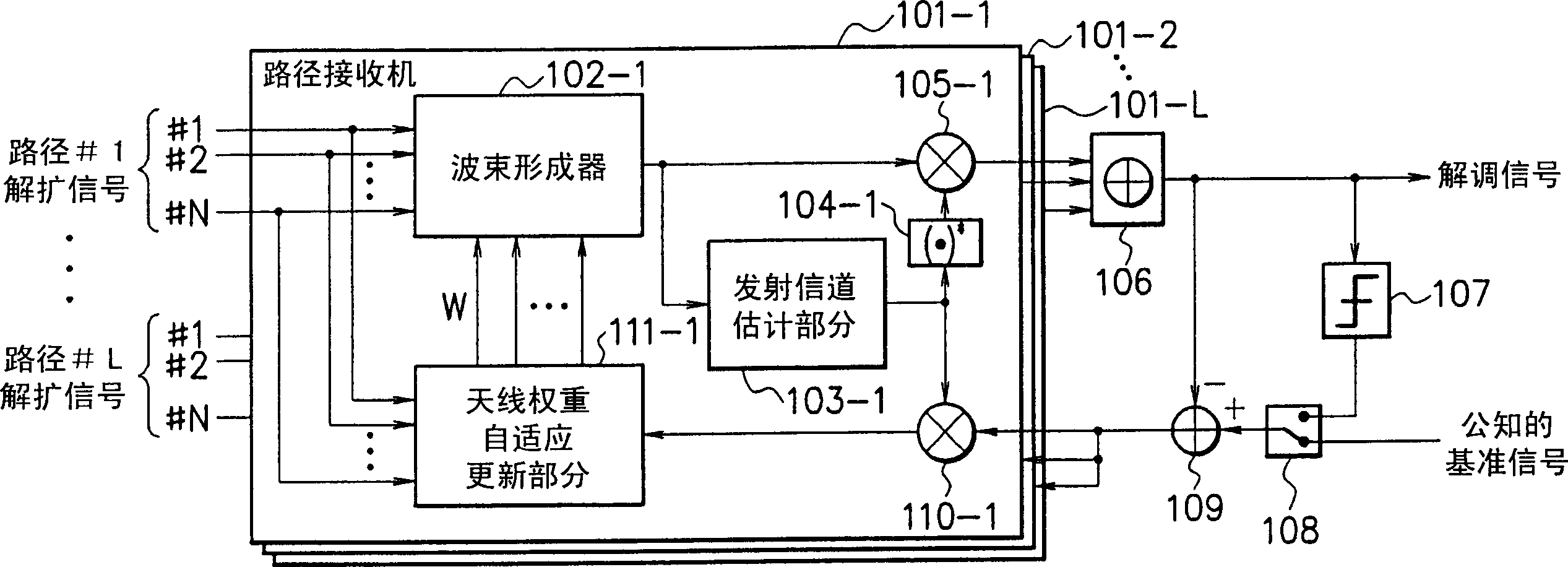
[0099] Figure 4 is a block diagram showing the configuration of an adaptive antenna receiver according to an embodiment of the present invention. refer to Figure 4 , the adaptive antenna receiver includes path receivers 1 - 1 to 1 -L, a combiner 6 , a determination unit 7 , a switch 8 and a subtractor 9 .

[0100]L path receivers 1-1 to 1-L are provided to perform multipath combining corresponding to multipath propagation channels in a mobile communication environment. All path receivers 1-1 to 1-L have the same constitution.

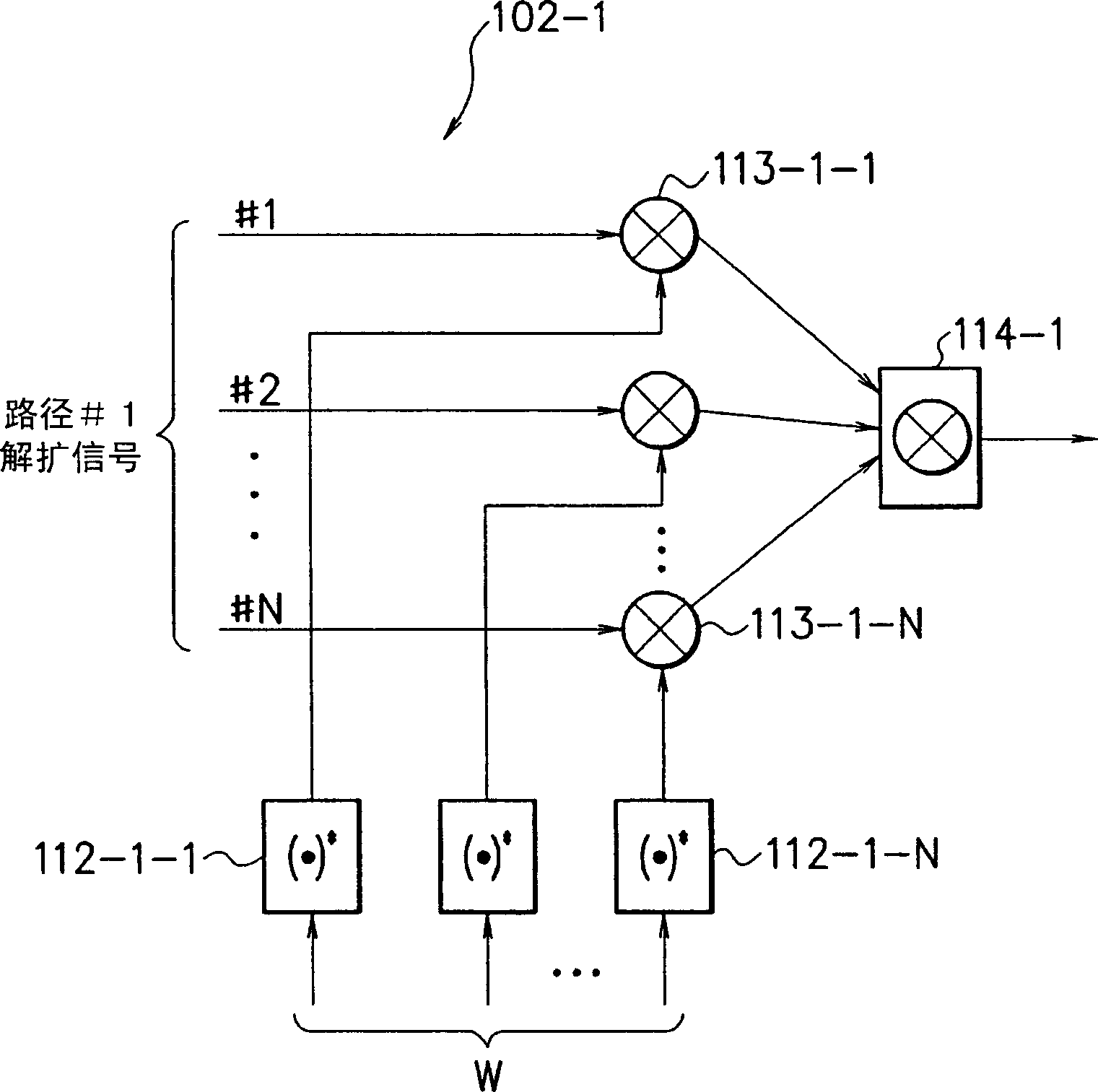
[0101] The path receiver 1-1 includes a beamformer 2-1, a transmit channel estimation part 3-1, a complex conjugate operation part 4-1, multipliers 5-1 and 10-1, and an antenna weight adaptive update part 11-1 , an antenna weight direction limiting section 12-1 and a direction vector generator 16-1.

[0102] The beamfor...


PUM


Abstract

There is provided an adaptive antenna reception device having an improved follow-up for an angle change of the coming direction of a desired signal. An antenna weight adaptive update means (11-1) adaptively updates the antenna weight from a signal received by each antenna element and an error signal obtained by using the desired signal corrected according to transmission path estimation. An antenna weight direction restraint means (12-1) performs restraint processing on the antenna weight obtained by the antenna weight adaptive update means (11-1) so that the beam gain is constant in the coming direction of the desired signal. A beam former (2-1) receives the desired signal by the array antenna by using the antenna weight subjected to the restraint processing in the antenna weight direction restraint means (12-1). Transmission path estimation means (3-1) estimates a transmission path of the desired signal received by the beam former (2-1) and corrects the desired signal by using the estimation result.

Description

technical field [0001] The present invention relates to an adaptive antenna receiver, and more particularly, to an adaptive antenna receiver for adaptively forming antenna directivity or The beam is directed so as to receive the desired signal from a particular user. Background technique [0002] CDMA (Code Division Multiple Access) systems have the potential to increase subscriber capacity relative to radio frequency and, as a wireless access system, are attractive for mobile communication cellular systems. [0003] However, there is a problem in the CDMA system that when a base station receives a desired signal from a specific user, interference occurs with other signals from users who simultaneously access the same base station as the specific user. In order to reduce such interference signals so that desired signals can be correctly received, an array antenna can be used. [0004] An array antenna includes a plurality of antenna elements. The array antenna weights eac...

Claims


Application Information

Patent Timeline
Patent Type & Authority Applications(China)
IPC IPC(8): H01Q3/26H04B7/10H04B1/707H04B7/08H04J99/00
CPCH04B7/0854H01Q3/2605
Inventor 吉田尚正
Owner NEC CORP
Why Eureka
Try Eureka