Rotor for motor and motor

A motor and rotor technology, applied in the field of motor rotors and motors, can solve the problems of large rotor inertia and heavy permanent magnet weight, and achieve the effects of small inertia and excellent follow-up.

Inactive Publication Date: 2011-05-04
NIDEC SANKYO CORP
View PDF6 Cites 10 Cited by
  • Summary
  • Abstract
  • Description
  • Claims
  • Application Information

AI Technical Summary

Problems solved by technology

However, in the rotor for an electric motor described in Patent Document 1, there is a prob

Method used


Image

  • Rotor for motor and motor
  • Rotor for motor and motor
  • Rotor for motor and motor

Examples


Embodiment Construction

[0040] Hereinafter, a stepping motor will be described as a motor using the present invention with reference to the drawings. In the following description, the "motor rotor" is referred to as "rotor".

[0041] (Structure of motor)

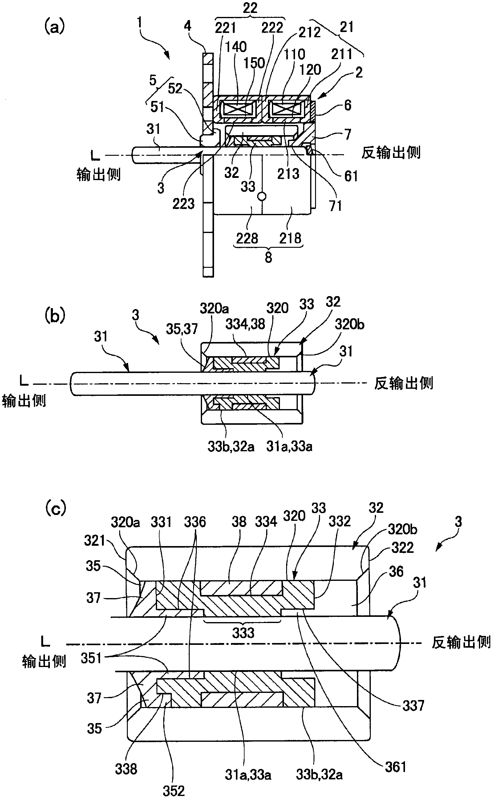
[0042] figure 1 is an explanatory diagram of a motor using the present invention, figure 1 (a) is a side view showing a part of the motor cut away, figure 1 (b) is a sectional view of the rotor (motor rotor), figure 1 (c) is an enlarged sectional view of a main part of the rotor.

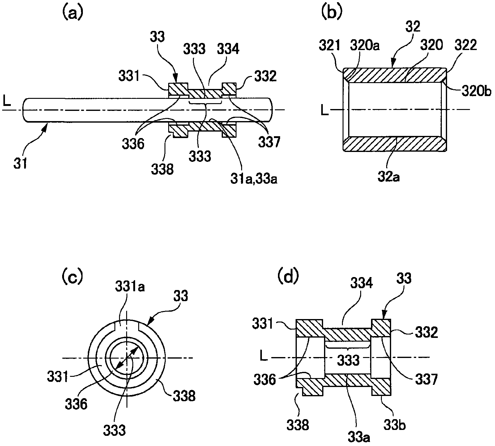
[0043] figure 1 The illustrated motor 1 is a stepping motor and includes: a cylindrical stator 2; and a rotor 3 (motor rotor) arranged on the inner peripheral side of the stator 2. As shown in FIG. The rotor 3 includes: a shaft 31 ; and a cylindrical permanent magnet 32 ​​coaxially attached to the outer peripheral side of the shaft 31 . In this embodiment, a sleeve 33 described later is attached between the shaft 31 and the permanent magnet 32 ​​.

[0044] A first...


PUM


Abstract

A rotor for a motor capable of implementing lightness and a motor having the rotor. In the rotor (3) of the motor (1), a sleeve (33) made of resin is disposed between an outer peripheral face (31a) of the rotation shaft (31) and an inner peripheral face (32a) of the permanent magnet (32), and press-fitted and fixed to the outer peripheral face of the rotation shaft (31). Thereby, wall thickness of the sleeve (33) is reduced by the permanent magnet (32) without reducing of external diameter of the permanent magnet (32). In addition, a first ring-shaped recessed part (35) is formed between the rotation shaft (31) and the permanent magnet (32), the rotation shaft (31), the sleeve (33) and the permanent magnet (32) are fixed one by one with an adhesive (37) in the first ring-shaped recessed part (35). In this case, the adhesive (37) is arranged in the first ring-shaped recessed part (35) and can not be retreated from one end part (321) of the permanent magnet (32) to an output end.

Description

technical field [0001] The invention relates to a rotor for a motor and the motor. Background technique [0002] Among various electric motors, for example, a stepping motor includes: a stator having a bobbin wound with a coil wire; and a stator member; and a rotor (motor rotor). The rotor has a cylindrical permanent magnet on the outer peripheral side of the rotating shaft, and conventionally, the permanent magnet is press-fitted and fixed to the rotating shaft (see Patent Document 1). [0003] Patent Document 1: Japanese Patent Laid-Open No. 2009-189236 [0004] In electric motors, it is desired to improve the following performance in a high-speed region, but for this purpose, it is necessary to reduce the inertia of the rotor. However, in the rotor for an electric motor described in Patent Document 1, there is a problem that the weight of the permanent magnets is large and the inertia of the rotor is large. Contents of the invention [0005] The present invention has...

Claims


Application Information

Patent Timeline
IPC IPC(8): H02K1/27H02K1/28
CPCH02K1/2733H02K1/30H02K37/14
Inventor 米山秀和
Owner NIDEC SANKYO CORP
Why Eureka
Try Eureka