Immersed tube tunnel final joints structure form and use method thereof
A technology of joint structure and immersed tube tunnel, which is applied in the direction of tunnel, earthwork drilling and mining, mining equipment, etc.
- Summary
- Abstract
- Description
- Claims
- Application Information
AI Technical Summary
Problems solved by technology
Method used
Image

Examples
Embodiment Construction
[0010] The features of the present invention and other related features will be further described in detail below with examples in conjunction with the accompanying drawings.
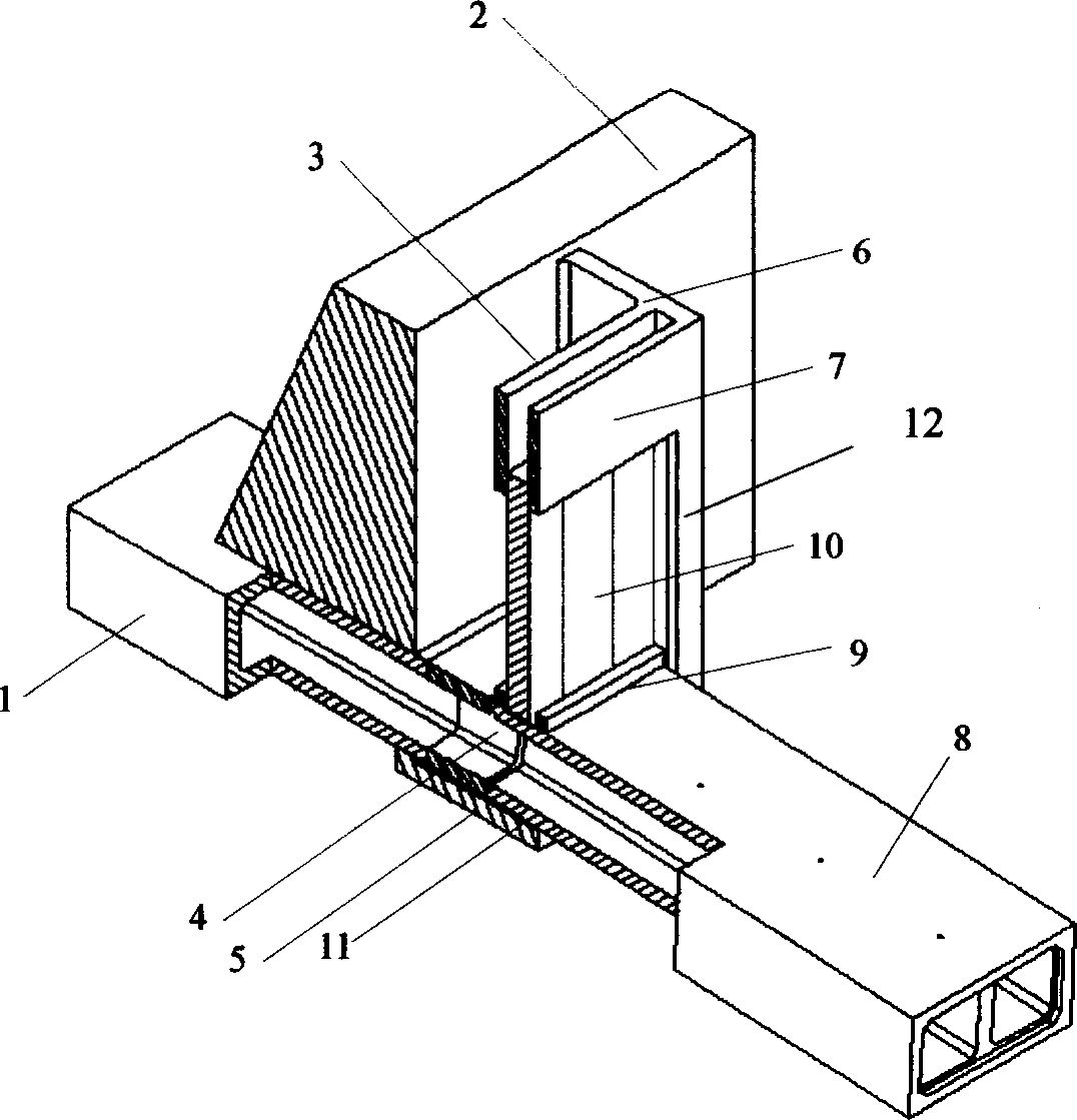
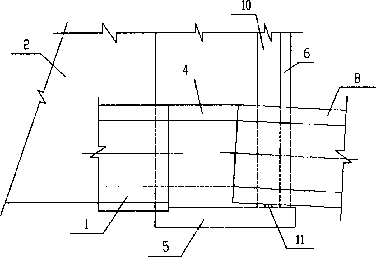
[0011] Such as figure 1 , 2 As shown, the numbers 1 to 12 respectively represent: buried section (1), water retaining embankment (2), joint well (3), final joint (4), joint well bottom plate (5), joint well side wall (6) , anti-wave parapet (7), the last sinking pipe section (8), thrust sill (9), vertical framing steel seal door (10), corbel (11) on the bottom plate of the joint well, and the well opening of the joint Mouth (12).
[0012] A subsea rectangular immersed tube tunnel has a pipe section width of 8.1m, a height of 4.4m, and a section length of 23.4m. Each tunnel has a total of 6 sections, which are sunk from the sea to the shore, and the final joint construction is carried out at the junction of water and land. Objective conditions determine that the dry dock cannot be selected at the axis...
PUM
 Abstract
Description
Claims
Application Information
 - R&D
- Intellectual Property
- Life Sciences
- Materials
- Tech Scout
- Unparalleled Data Quality
- Higher Quality Content
- 60% Fewer Hallucinations
Browse by: Latest US Patents, China's latest patents, Technical Efficacy Thesaurus, Application Domain, Technology Topic, Popular Technical Reports.
© 2025 PatSnap. All rights reserved.Legal|Privacy policy|Modern Slavery Act Transparency Statement|Sitemap|About US| Contact US: help@patsnap.com