Electric bicycle drive wheel balance frame structure

A frame structure and driving wheel technology, applied to bicycle brackets, bicycle accessories, axle suspension devices, etc., can solve the problems of excessive acceleration of the driver, dumping of the scooter, and defects in driving stability, so as to prevent the failure of the power wheel Effect

Inactive Publication Date: 2006-08-09
PIHSIANG MACHINERY MFG
View PDF0 Cites 2 Cited by
  • Summary
  • Abstract
  • Description
  • Claims
  • Application Information

AI Technical Summary

Problems solved by technology

[0003] Traditional fixed frame designs such as figure 1 As shown, all the frames 10 are combined and fixed one by one to allow the user to operate and drive, and the heavier equipment such as batteries, motors, and controllers are placed under the operator's seat to concentrate the driving center of gravity (Improve handling); however, for users with limited mobility, the frame structure design of the aforementioned electric scooter is not ideal, and there are major defects in driving stability; please refer to the first picture and the detailed description as follows:
[0004] First, for disabled persons with limited mobility or physical disabilities, it is inevitable to encounter cornering situations when driving on the road, but because the body movements of scooter drivers are not as flexible as normal people, even the simplest body Shifting the center of gravity is also a very difficult action; however, the frame body 10 of the current stationary scooter is prone to inclination of t

Method used


Image

  • Electric bicycle drive wheel balance frame structure
  • Electric bicycle drive wheel balance frame structure
  • Electric bicycle drive wheel balance frame structure

Examples


Embodiment Construction

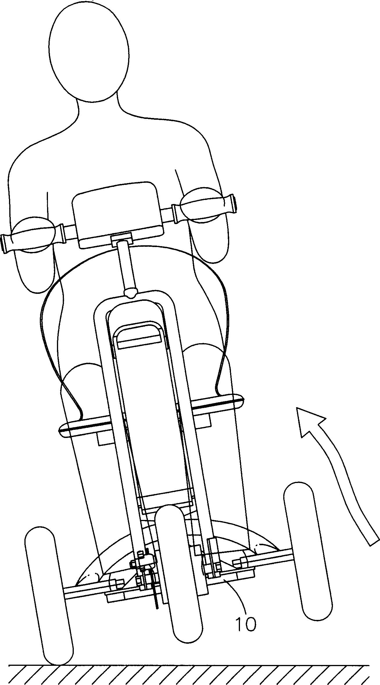
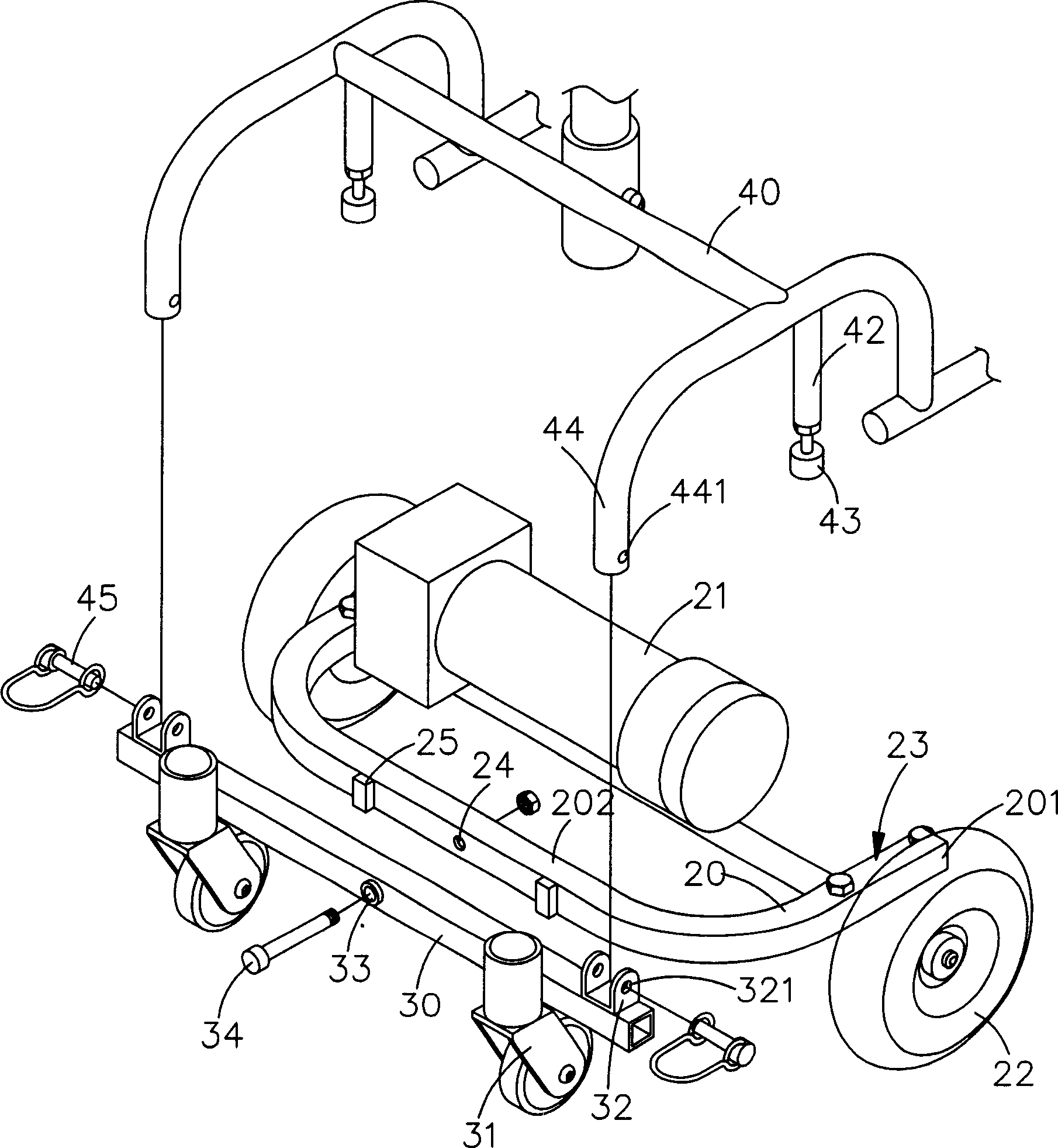
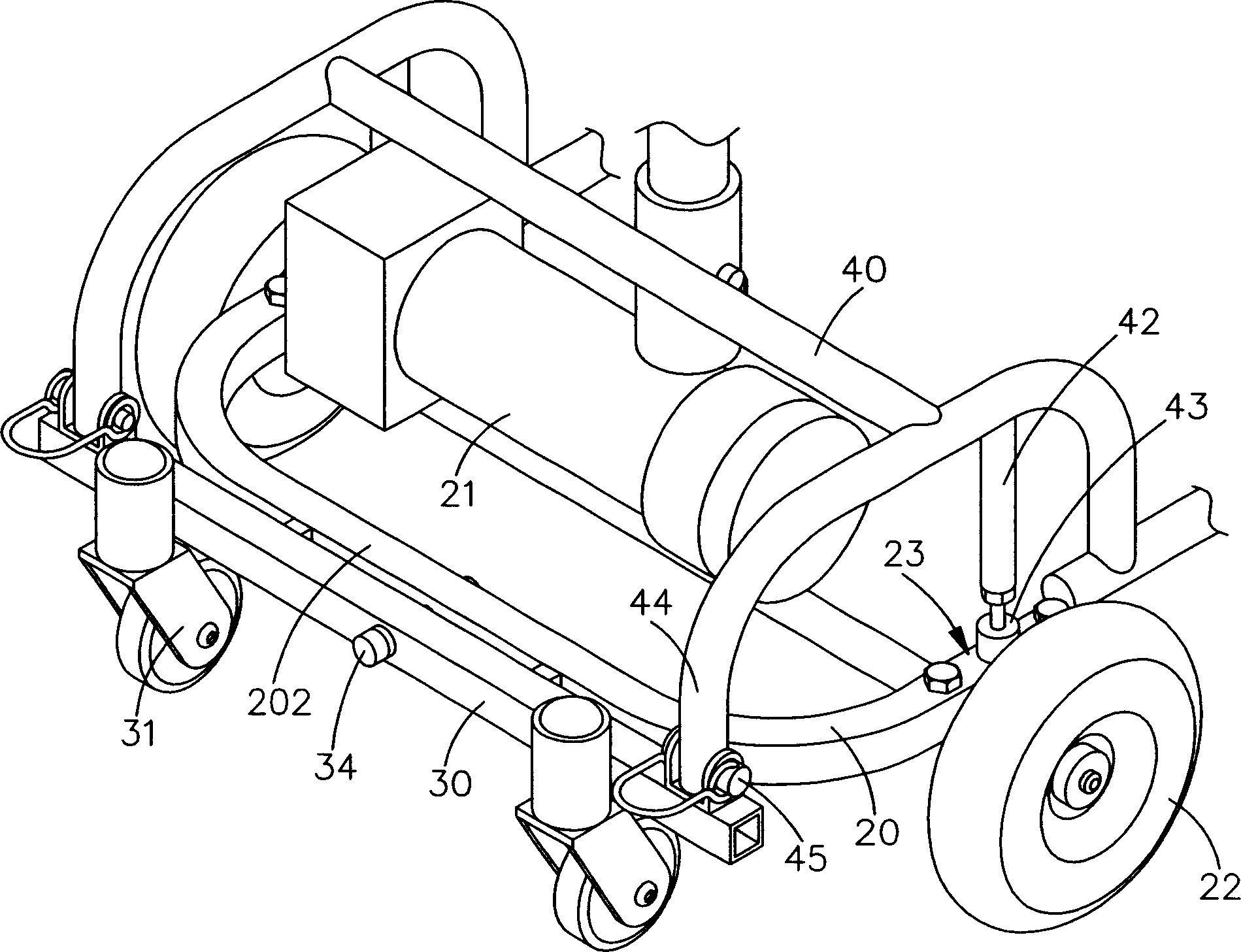
[0046] First please refer to Figure 2-4 Shown:

[0047] The electric vehicle drive wheel balance frame structure of the present invention includes a power wheel frame 20, an auxiliary wheel frame 30 and a weight support frame 40; its structural features are:

[0048]The power wheel frame 20 is a slightly ㄩ-shaped frame body, on which a power motor 21 and a power wheel 22 are installed, and the two protruding ends 201 of the ㄩ-shaped power wheel frame 20 are set at preset positions. There is a top portion 23, and a first pivot hole 24 is opened in the center of the horizontal frame portion 202 opposite to the two protruding ends 201. The axial direction of the first pivot hole 24 is perpendicular to the direction of the wheel axis of the power wheel 22, and the first pivot hole 24 An anti-collision assembly 25 is installed on the side;

[0049] The auxiliary wheel frame 30 is a slightly in-line frame body, and two auxiliary wheels 31 are installed at its rear end, and a pivo...


PUM


Abstract

The invention relates to the vehicle frame used for balancing the driving wheels of the electric vehicle, it is designed to detach the vehicle frame supporting the weight of the manipulator from the driving wheel frame, and it connects the assistant wheel frame and the driving wheel frame by the hub, the assistant wheel frame and the pintle of the power ring frame of the vehicle parallel the axle, the assistant wheel frame connects the driving wheel frame of the vehicle by the hub,the assistant wheel frame and the pintle of the driving wheel frame of the vehicle intersect the axle vertically, the cushioning groupware is mounted between the weight supporting frame and the driving wheel frame; so, the invention can apply the assistant wheel frame conjugating the weight supporting frame to swing the barycenter, and the movement of the driving wheel frame does not come under the shift of the barycenter of the handlers, spanning the rank of the road and wheeling high speed. The driving wheel is suppressed by the driving wheel frame on the road, so the abating of the driving wheel and the falling of the vehicle are avoided effectively. The invention is the vehicle frame used for balancing the driving wheels of the electric vehicle of increasing the stability of spinning the steps of the road and wheeling steering.

Description

technical field [0001] The invention relates to a frame of an electric scooter, more specifically, a designer of a balanced frame structure for driving wheels of an electric vehicle that can increase the stability of cornering. Background technique [0002] As modern people pay more and more attention to the impact of living space on health and psychology, and the frail elderly and patients with limited mobility can only live in a limited indoor space without means of transportation, therefore, electric scooters on the market today occupy a considerable market. [0003] Traditional fixed frame designs such as figure 1 As shown, all the frames 10 are combined and fixed one by one to allow the user to operate and drive, and the heavier equipment such as batteries, motors, and controllers are placed under the operator's seat to concentrate the driving center of gravity (Improve handling); however, for users with limited mobility, the frame structure design of the aforemention...

Claims


Application Information

Patent Timeline
IPC IPC(8): B62H1/12B62K25/04
Inventor 伍必翔
Owner PIHSIANG MACHINERY MFG
Why Eureka
Try Eureka