Method for the production of a stator and stator produced according thereto

A manufacturing method and technology of motor stator, which are applied in the manufacture of stator/rotor body, motor generator, magnetic circuit shape/style/structure, etc., can solve problems such as increasing the outer diameter of the motor, and achieve different degrees of clamping reduction. , Accurately determine and improve the effect of fixation

Inactive Publication Date: 2007-01-24
SEG AUTOMOTIVE GERMANY GMBH
View PDF1 Cites 12 Cited by
  • Summary
  • Abstract
  • Description
  • Claims
  • Application Information

AI Technical Summary

Problems solved by technology

The placement of these bolts on the outer circumference of the stator increases the outer diameter of the motor

Method used


Image

  • Method for the production of a stator and stator produced according thereto
  • Method for the production of a stator and stator produced according thereto
  • Method for the production of a stator and stator produced according thereto

Examples


Embodiment Construction

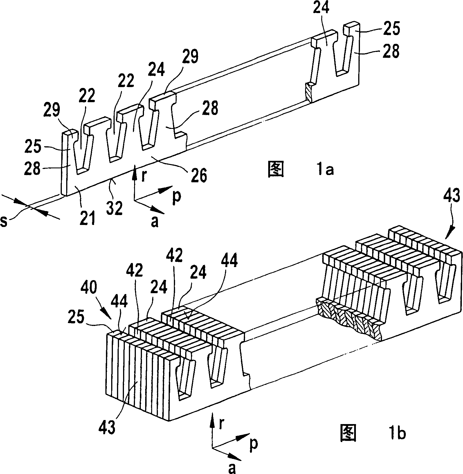
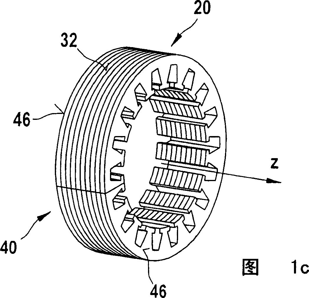
[0038] Figures 1a, 1b and 1c show the basic method of manufacturing a stator core 20 of an electrical machine manufactured according to the so-called lamination process. First, a substantially rectangular or cuboid-shaped strip 21 is provided, which has notches 22 . Both sides of these notches 22 are delimited by teeth 24 or half teeth 25 , respectively. The individual teeth 24 or half-tooths 25 are connected to each other via a yoke 26 . The yoke 26 extends substantially in the circumferential direction p and in the radial direction r, moreover it generally has a material thickness s which corresponds to the thickness of the lamination 21 . The yoke 26 has a yoke back 32 facing away from the tooth 24 or half-tooth 25 . The back face 32 of the yoke is oriented opposite to the direction r. The teeth 24 and the half-tooths 25 extend essentially in the radial direction r and in the circumferential direction p. The teeth 24 and half teeth 25 also have a material thickness s. ...


PUM

PropertyMeasurementUnit
thicknessaaaaaaaaaa
lengthaaaaaaaaaa

Abstract

A method for manufacturing a stator core (20) of an electric motor, wherein first a substantially rectangular parallelepiped-shaped sheet group (40) is formed from strip-shaped sheets (21), and the sheet group is wound around a circular shaft core in a subsequent step. The roll is deformed into an annular shape having an axial direction (a) corresponding to the cylinder axis (z), wherein the annular shape has an axial end face (46). In this case, in a further subsequent step, the annular lamella group ( 40 ) is plastically deformed in the axial direction (a) at least partially on the axial end face ( 46 ). The stator of an electric machine, in particular an automobile generator, comprises a stator core composed of strip-shaped sheets (21) wound around a circular shaft core, the stator core having axial end faces (46). The stator core is plastically deformed in the axial direction (a) on the end face (46). The stator of an electric machine, in particular an automobile generator, comprises a stator core composed of strip-shaped sheets (21) wound around a circular shaft core, the stator core having axial end faces (46). The axial length of the stator core on its inner diameter is greater than the axial length on its outer diameter.

Description

technical field [0001] The invention relates to a method of manufacturing a stator according to the preambles of the independent claims and to a stator manufactured by this method. Background technique [0002] WO 01 / 54254 A1 discloses a method of manufacturing a stator for an electrical machine, in particular a generator for an automobile. For this purpose, an essentially cuboid-shaped sheet pack is first produced from strip-shaped sheets, which in a subsequent step is shaped into a ring shape by bending around a circular axis. The ring shape of the stator or stator core has two axial end faces. It has been established that a stator or stator core of this type, which is axially clamped between two end shields via the axial end faces, has greater axial elasticity and flexibility. This flexibility leads to loose fastening elements, such as bolts, which are used to clamp the stator between the endshields, or must be able to withstand high loads, which has an impact on the di...

Claims


Application Information

Patent Timeline
Patent Type & Authority Applications(China)
IPC IPC(8): H02K1/06H02K1/18H02K15/02H02K1/16
CPCY10T29/49009H02K1/16H02K15/024
Inventor E·劳T·贝格尔M·亨内K·普夫吕格尔
Owner SEG AUTOMOTIVE GERMANY GMBH
Why Eureka
Try Eureka