
Work assembling device and assembling method

A technology for assembling devices and workpieces, applied in positioning devices, metal processing machinery parts, assembling machines, etc., can solve the problems of limited space and work efficiency, and achieve the effect of easy operation and simple structure

Inactive Publication Date: 2010-05-12
HONDA MOTOR CO LTD
View PDF11 Cites 0 Cited by
  • Summary
  • Abstract
  • Description
  • Claims
  • Application Information

AI Technical Summary

Problems solved by technology

[0019] In the case of a method in which a workpiece inversion process is provided in the middle of a series of processes such as handling and processing as in Patent Document 5, when a workpiece has a component assembly surface on multiple surfaces, it is necessary to provide a plurality of workpiece inversion processes. In terms of space There is also a limit to work efficiency

Method used


Image

  • Work assembling device and assembling method
  • Work assembling device and assembling method
  • Work assembling device and assembling method

Examples


Embodiment Construction

[0063] Embodiments of the present invention will be described with reference to the drawings.

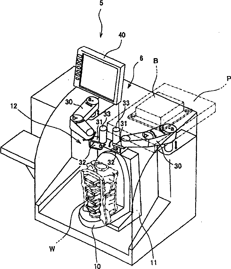
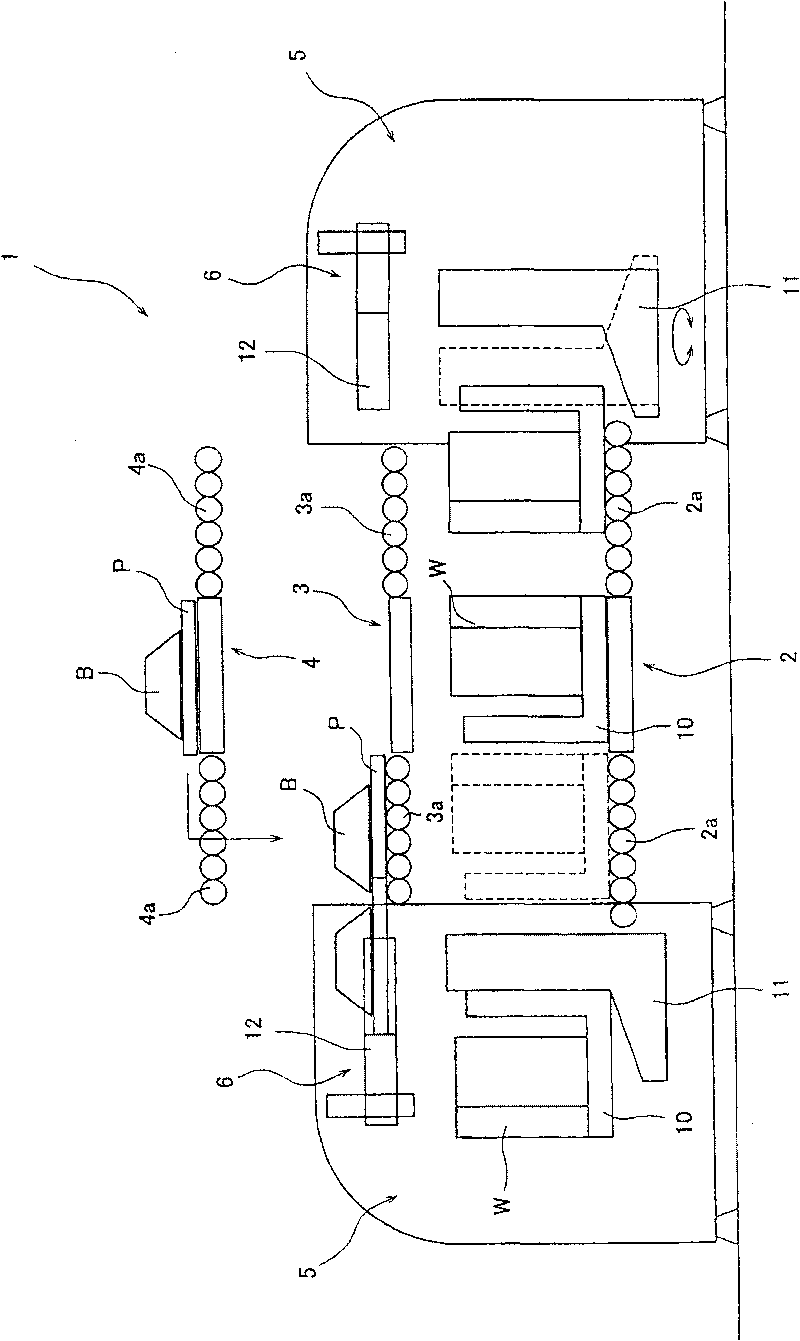
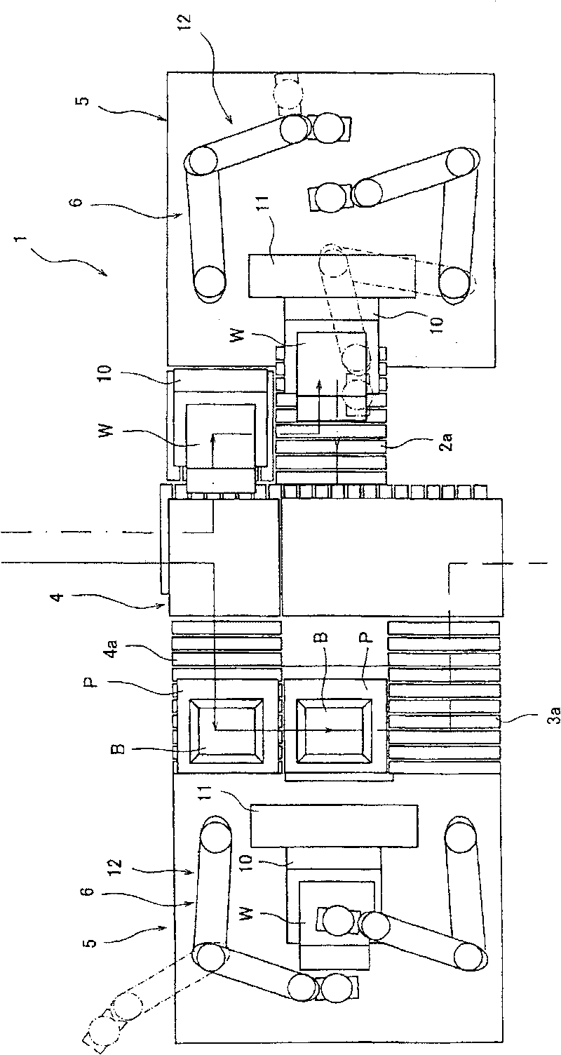
[0064] here, figure 1 It is a perspective view showing the appearance of this workpiece mounting device, figure 2 It is the front view of the whole workpiece assembly system, image 3 is the plan view of the same workpiece assembly system, Figure 4 is an explanatory diagram of the workpiece holding jig and column, Figure 5 It is an explanatory diagram of the internal structure of the workpiece holding jig, Figure 6 It is an explanatory diagram showing an example of changing the posture of the workpiece by the workpiece holding jig, Figure 7 It is an explanatory diagram of the state of holding parts with the parts holding device, Figure 8 It is an explanatory diagram showing the advantage of vertical assembly.

[0065] The workpiece assembly device of the present invention can efficiently assemble a workpiece having component assembly surfaces on multiple surfaces, and ca...


PUM


Abstract

A work holding jig (10) rotates a work (W) having component assembling surfaces on its multi-surface to move the component assembling surfaces successively to an upwardly-tilted horizontal position, and from above, a component gripper (12) grips an assembly component (B) to vertically tighten bolts. By repeating this operation, assembling work can be smoothly performed and space saving for assembling space can be attained.

Description

technical field [0001] The present invention relates to a workpiece assembling device and an assembling method that facilitate, for example, the assembly of various parts while conveying a workpiece. Background technique [0002] In the past, as a device for assembling various assembly parts while conveying workpieces, for example, such a technical solution is known, that is, an auxiliary pallet that can freely rotate relative to the pallet body is provided, and the workpiece is fixed on the auxiliary pallet to be conveyed, and after conveying After arriving at the assembly part, the auxiliary pallet is tilted at a predetermined angle and positioned, so that the workpiece can be changed to a predetermined posture to facilitate the assembly work (for example, refer to Patent Document 1). [0003] As an apparatus for supplying press-fit parts to a press-fit part of a workpiece and press-fitting them, for example, a device is known in which the press-fit parts are held by the w...

Claims


Application Information

Patent Timeline
Patent Type & Authority Patents(China)
IPC IPC(8): B23P19/00B23P21/00B23P19/06
CPCB23P19/06B23P19/001Y10T29/49902Y10T29/49947Y10T29/49778Y10T29/49895Y10T29/49998Y10T29/53961Y10T29/49897Y10T29/53061Y10T29/53052B23P19/00B23Q3/06
Inventor 吉田尚山田宗干石井哲夫椋本隆次
Owner HONDA MOTOR CO LTD
Learn More