An apparatus for discharging a residual part of a resin tube in an automatic bookbinding machine

A residual resin, automatic binding technology, applied in the book binding, binding, printing and other directions, can solve the problem of the length of the resin tube cannot be confirmed from the outside, difficult to use the resin tube effectively, injury and other problems

Inactive Publication Date: 2007-03-21
NAKABAYASHI CORP
View PDF2 Cites 2 Cited by
  • Summary
  • Abstract
  • Description
  • Claims
  • Application Information

AI Technical Summary

Problems solved by technology

That is, a special tool is required to remove the resin tube
In addition, since the dedicated tool is long and its insertion position is the top surface of the main body of the binding machine, it is extremely laborious to take out the residual resin tube.
Also, since the head of the special tool is thin, there is a risk of injury, so it must be handled with care.
In addition, the length of the remaining resin tube cannot be confirmed from the outside, and it is taken out when it does not meet the thickness at the time of binding thickness measurement. Since the binding thickness is thinner, it may be used as it is, so it is difficult to effectively use the resin tube. Sometimes there is waste

Method used


Image

  • An apparatus for discharging a residual part of a resin tube in an automatic bookbinding machine
  • An apparatus for discharging a residual part of a resin tube in an automatic bookbinding machine
  • An apparatus for discharging a residual part of a resin tube in an automatic bookbinding machine

Examples


Embodiment Construction

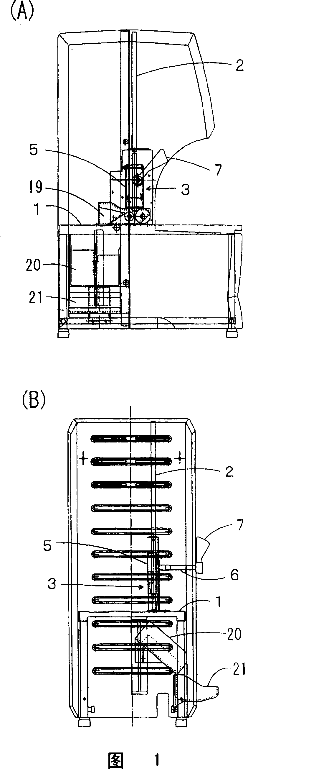
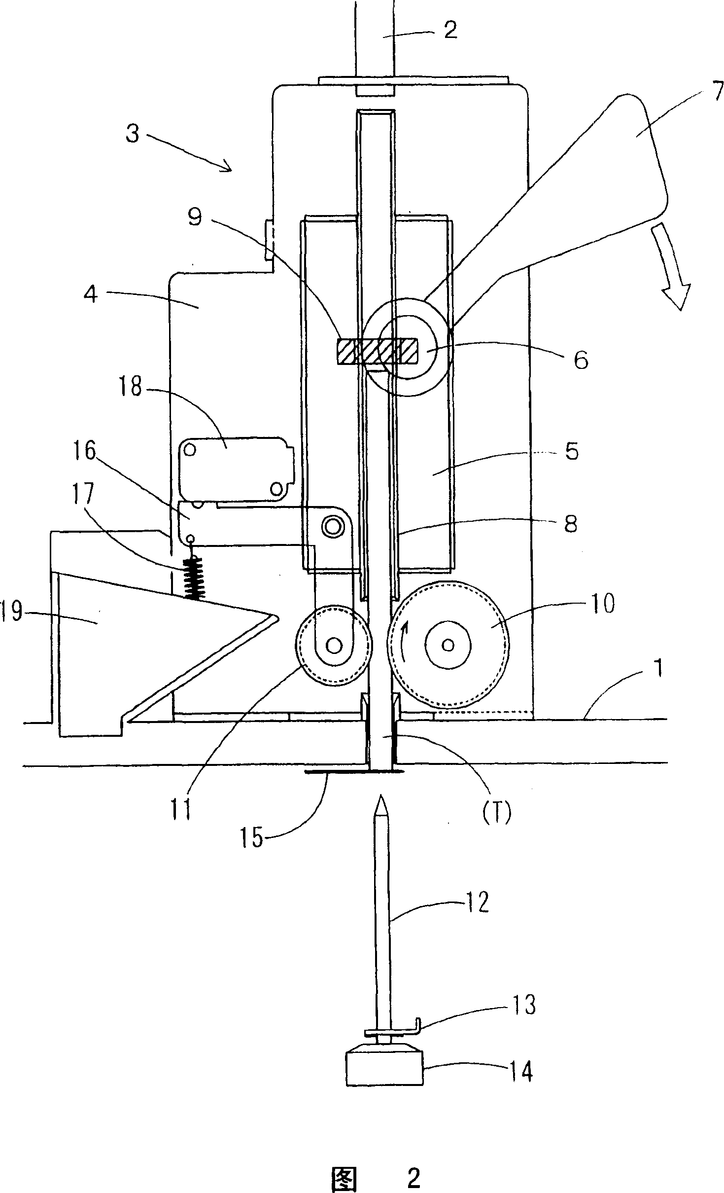
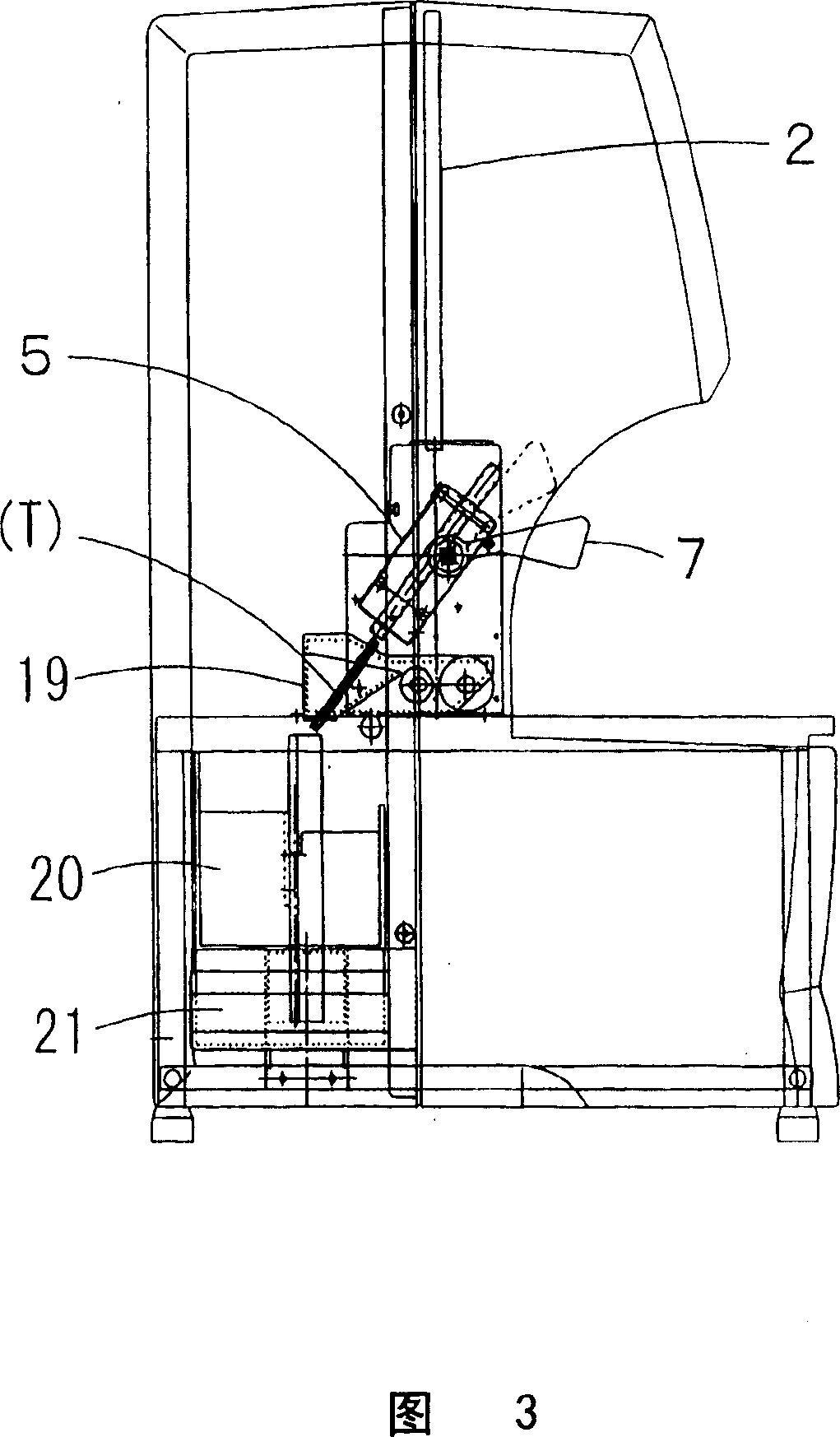
[0039] Next, preferred embodiments of the discharge device for residual resin tubes according to the present invention will be described with reference to the drawings. Fig. 1 (A) is a side view of the automatic binding machine, and Fig. 1 (B) is a rear view, both of which show the positional relationship of the discharge device of the present invention in the whole. In addition, FIG. 2 is a schematic configuration diagram of a discharge device for residual resin tubes.

[0040] In Fig. 1 and Fig. 2, 1 is the base of automatic binding machine, and the device that is used for piercing the binding hole on the document, the device that supplies the resin tube of each expected length, and the device that forms binding bar are respectively installed (all not shown in the figure). ). 2 is a resin tube conduit installed vertically downward from the top surface of the main body of the automatic binding machine, and actually supplies long resin tubes to the above-mentioned device for ...


PUM


Abstract

A residual resin tube discharging device of an automatic bookbinding machine using a resin tube is provided to discharge residual resin tubes without a jig by operating a discharge lever by a user if a resin tube detecting sensor determines that the resin tube remaining in the bookbinding machine is shorter than the standard length. The residual resin tube discharging device(3) of an automatic bookbinding machine using a resin tube is composed of a resin tube bracket(5) movably installed at a resin tube transfer base(4) set up on a base plate(1) of the automatic bookbinding machine through a turning shaft(6); a discharge lever(7) attached to the turning shaft; a resin tube holding pipe(8) installed at the resin tube bracket to communicate with a resin tube guide pipe(2); and a resin tube detecting sensor(9) mounted on a predetermined spot of the resin tube holding pipe. If the resin tube is not detected by the resin tube detecting sensor and the resin tube is short, the residual resin tubes are returned into the resin tube holding pipe by reversely turning a resin tube transfer roller(10) by a control device and the discharge lever is operated by urging a user to operate the discharge lever. And then, the resin tube bracket is turned to fall the resin tube remaining in the resin tube holding pipe to a resin tube discharge guide(19).

Description

technical field [0001] The present invention relates to a discharge device, which can easily discharge the remaining resin tube in an automatic binding machine that uses a resin tube as a binding rod to bind documents when the length of the remaining resin tube does not reach the length required for binding. Resin tube. Background technique [0002] Heretofore, the present applicant independently developed, manufactured and sold an automatic binding machine that uses a resin tube as a binding rod to bind documents. As shown in Patent Document 1, the basic principle of the paper binding method of this automatic binding machine is to insert a resin tube with an appropriate length into the binding hole provided on the paper, and heat the two ends of the resin tube by a stamper to form Flange-like protrusion. Moreover, the basic structure of the automatic binding machine for automatically implementing the said stapling principle is the structure shown in patent document 2, for...

Claims


Application Information

Patent Timeline
Patent Type & Authority Applications(China)
IPC IPC(8): B42B5/00
CPCB42B5/02B42C99/00
Inventor 寺本高
Owner NAKABAYASHI CORP
Why Eureka
Try Eureka