Fiber Cutting System
A technology of optical fiber and components, which is applied in the field of optical fiber cutting system, and can solve the problems of wrong movement of knife parts and unused knife parts, etc.
- Summary
- Abstract
- Description
- Claims
- Application Information
AI Technical Summary
Problems solved by technology
Method used
Image

Examples
no. 1 approach 〕
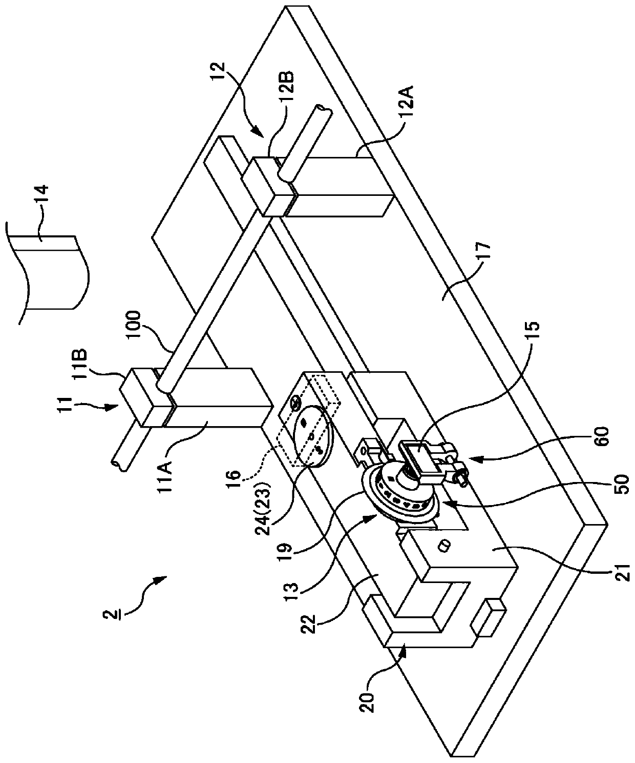
[0041] figure 1 It is a block diagram showing the optical fiber cutting system of the first embodiment. figure 2 It is a perspective view showing a structural example of the optical fiber cutting system of the first embodiment.
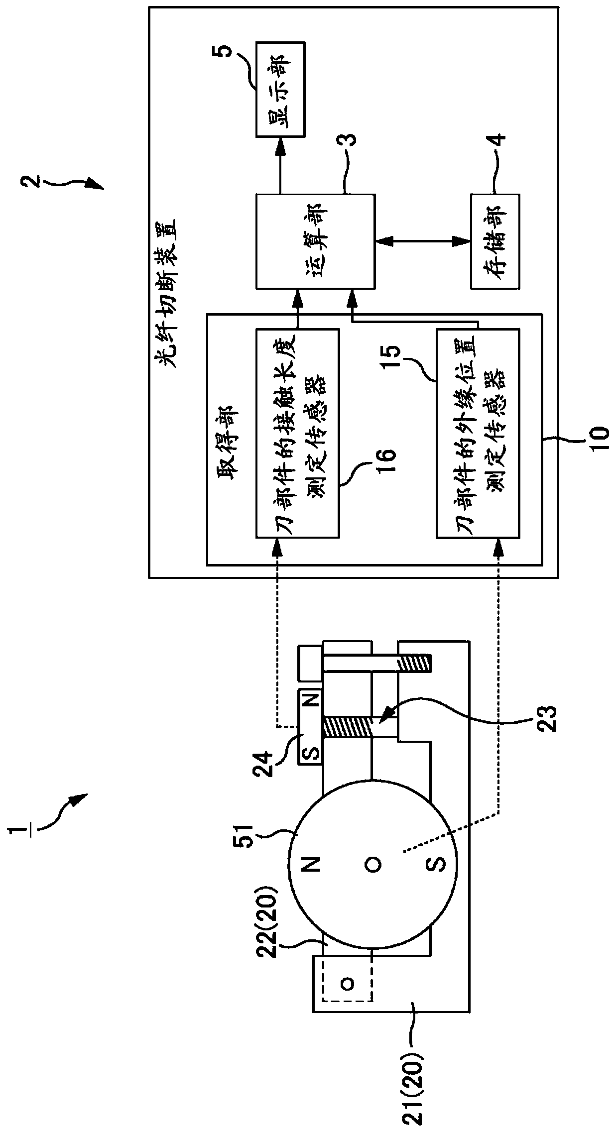
[0042]The optical fiber cutting system 1 includes: an optical fiber cutting device 2 including a knife member 13 for cutting (cleaving) an optical fiber 100 (optical fiber core); In addition, the optical fiber cutting system 1 of the present embodiment includes a calculation unit 3 for processing position information of the blade member 13 , a storage unit 4 , and a display unit 5 .
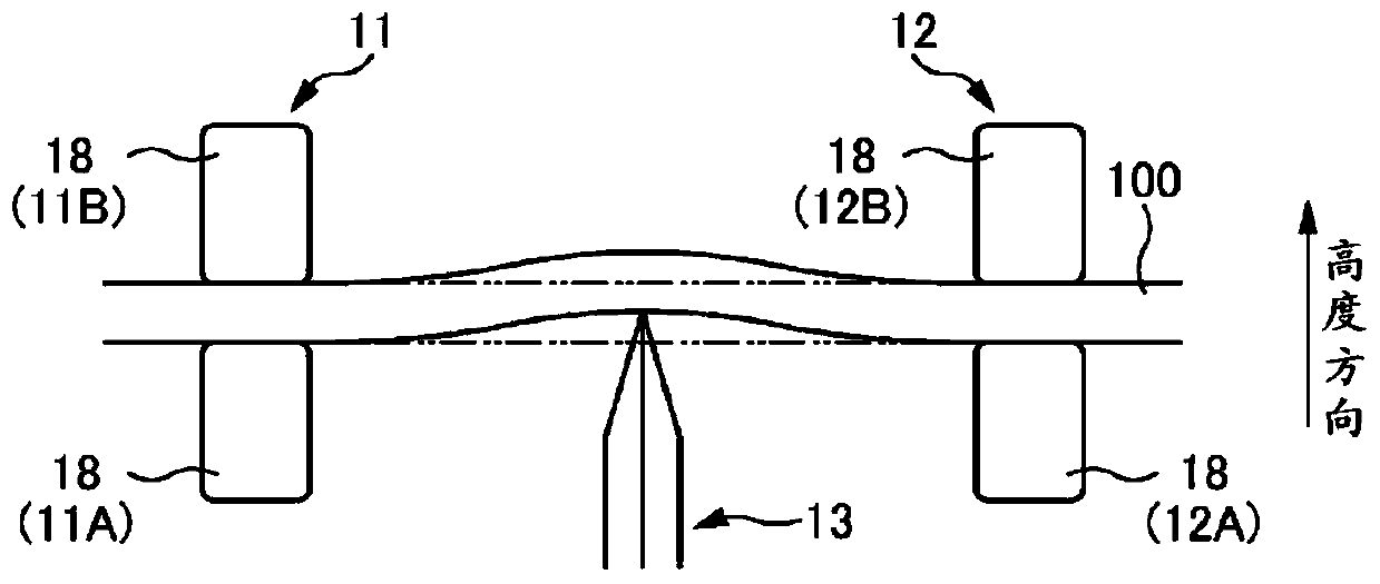
[0043] The optical fiber cutting device 2 includes a pair of clamps 11 and 12 , a knife member 13 and a pressing member 14 . A pair of jigs 11 and 12 and a knife member 13 are arranged on a base 17 of the optical fiber cutting device 2 . Although not shown in particular, the pressing member 14 is similarly arranged on the base 17 .
[0044] A pair of clamps 11 and 1...
no. 2 approach 〕
[0113] Next, for the second embodiment, refer to Figure 8 The description will focus on points different from the first embodiment. In addition, the same code|symbol is attached|subjected to the structure common to 1st Embodiment, and the description is abbreviate|omitted.
[0114] Such as Figure 8As shown, the optical fiber cutting system 1A of this embodiment includes an optical fiber cutting device 2A, an outer edge position measuring sensor 15 , a contact length measuring sensor 16 , a calculation unit 3 , a storage unit 4 , and a display unit 5 , as in the first embodiment. The configuration of the optical fiber cutting device 2A may be the same as that of the optical fiber cutting device 2 of the first embodiment. The outer edge position measurement sensor 15 and the contact length measurement sensor 16 are provided in the optical fiber cutting device 2A as in the first embodiment. In addition, the functions of the calculation unit 3 , the storage unit 4 , and the d...
no. 3 approach 〕
[0122] Next, for the third embodiment, refer to Figure 9 The description will focus on points different from the first and second embodiments. In addition, the same code|symbol is attached|subjected to the structure common to 1st, 2nd embodiment, and description is abbreviate|omitted.
[0123] Such as Figure 9 As shown, the optical fiber cutting system 1B of this embodiment includes an optical fiber cutting device 2B, an outer edge position measuring sensor 15 , a contact length measuring sensor 16 , a calculation unit 3 , a storage unit 4 , and a display unit 5 as in the first embodiment. The configuration of the optical fiber cutting device 2B may be the same as that of the optical fiber cutting device 2 of the first embodiment. The outer edge position measurement sensor 15 and the contact length measurement sensor 16 are provided in the optical fiber cutting device 2B as in the first embodiment. In addition, the functions of the calculation unit 3 , the storage unit 4 ...
PUM
 Abstract
Description
Claims
Application Information
 - R&D Engineer
- R&D Manager
- IP Professional
- Industry Leading Data Capabilities
- Powerful AI technology
- Patent DNA Extraction
Browse by: Latest US Patents, China's latest patents, Technical Efficacy Thesaurus, Application Domain, Technology Topic.
© 2024 PatSnap. All rights reserved.Legal|Privacy policy|Modern Slavery Act Transparency Statement|Sitemap