Oil supplier

A technology of fuel supply device and fuel oil, which is applied in the direction of charging system, engine components, liquid fuel feeder, etc., and can solve the problem that the setting of sub-fuel tanks is meaningless

Inactive Publication Date: 2004-06-16
MITSUBA CORP
View PDF2 Cites 1 Cited by
  • Summary
  • Abstract
  • Description
  • Claims
  • Application Information

AI Technical Summary

Problems solved by technology

Therefore, although a sub-tank is provided, the setting of the sub-tank is meaningless because the fuel in it must be discharged to the outside of the sub-tank

Method used


Image

  • Oil supplier
  • Oil supplier
  • Oil supplier

Examples


Embodiment Construction

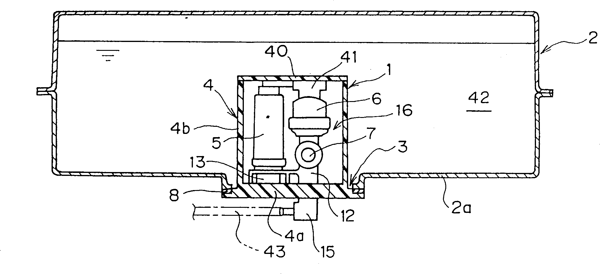
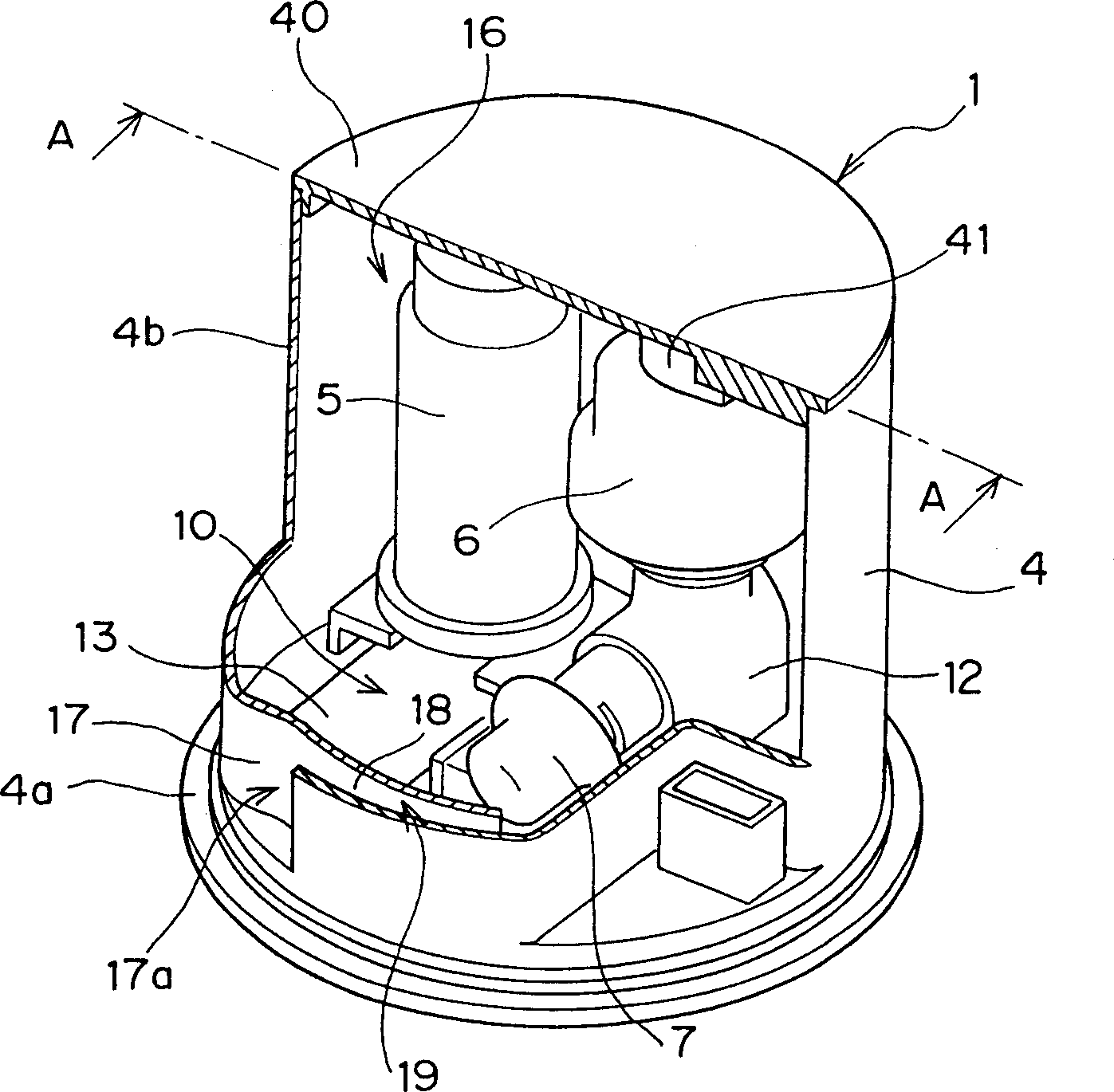
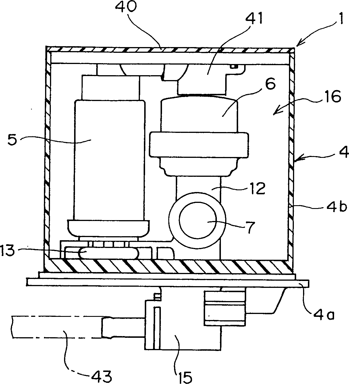
[0024] figure 1 It schematically shows the cross-sectional structure of the first embodiment of the oil supply device according to the present invention, and shows the position and installation relationship of the device, figure 2 yes figure 1 Partial cut-away schematic diagram of the embodiment of the oil supply device in . image 3 is along figure 2 Middle A-A line pair figure 1 Schematic diagram of the section made in the embodiment.

[0025] The fuel supply device 1 in this embodiment (hereinafter will simply be referred to simply as "device") is suitable as an in-tank type gasoline delivery device used in motorcycles. like figure 1 As shown, the device 1 is fitted to an opening 3 formed through the bottom 2 a of the fuel tank 2 from below. like figure 2 As shown, the device includes a cap-shaped flange (flange) 4, a fuel pump 5, a filter 6, an oil pressure regulator 7 and other components are installed in the flange, the device 1 It also includes a cover pl...


PUM


Abstract

This fuel system is composed of a bottom plate for closing an opening in the bottom surface of a fuel tank and a side wall part integrally formed with the bottom plate, and a space in the side wall part has a flange forming a sub tank in the fuel tank. A fuel pump, a strainer and a pressure regulator are arranged in the space in the side wall part, and return fuel in the pressure regulator is returned to the inside of the sub tank. A cover with a connecting member equipped with a fuel channel for connecting the fuel pump with the strainer is attached to the upper part of the side wall part. The connecting member retains the fuel pump and the upper part of the strainer. This fuel system is compact with easy installation, and can stably supply fuel to the engine.

Description

technical field [0001] The present invention relates to an in-tank fuel supply, and more particularly to a technique ideally applicable to a type of fuel supply particularly adapted to be mounted to the bottom of a fuel tank. Background technique [0002] Generally, a so-called in-tank fuel supply device widely used in the field of motorcycles or motor vehicles includes a fuel pump and a fuel filter arranged in a fuel tank, such a fuel supply device is disclosed in Japanese Patent Application Laid-Open Document Those devices disclosed in Hei 10-213036 and Hei 8-225023. Such tank-type oil supply devices can be divided into two major categories structurally, the first category includes Japanese Patent Application Laid-Open Document Hei 10-213036, and is shown in Figure 5 The kind of device in, this kind of oil supply device is suitable for fitting on the bottom opening 52 of fuel tank 51. The second category includes those disclosed in Japanese Patent Application Laid-Open D...

Claims


Application Information

Patent Timeline
Patent Type & Authority Patents(China)
IPC IPC(8): B60K15/03F02M37/00F02M37/10F02M37/22
CPCF02M37/106F02M37/103
Inventor 成嶋雅彦森信也
Owner MITSUBA CORP
Why Eureka
Try Eureka