
Heating, ventilating and/or air conditioning device with improved acoustics

A technology of air-conditioning units and channels, which is applied in heating/cooling equipment, noise suppression, transportation and packaging, etc., and can solve problems such as difficulty in standardization of parts

Active Publication Date: 2007-03-28
VALEO SYST THERMIQUES
View PDF1 Cites 3 Cited by
  • Summary
  • Abstract
  • Description
  • Claims
  • Application Information

AI Technical Summary

Problems solved by technology

Such a step makes standardization of this part difficult

Method used


Image

  • Heating, ventilating and/or air conditioning device with improved acoustics
  • Heating, ventilating and/or air conditioning device with improved acoustics
  • Heating, ventilating and/or air conditioning device with improved acoustics

Examples


Embodiment Construction

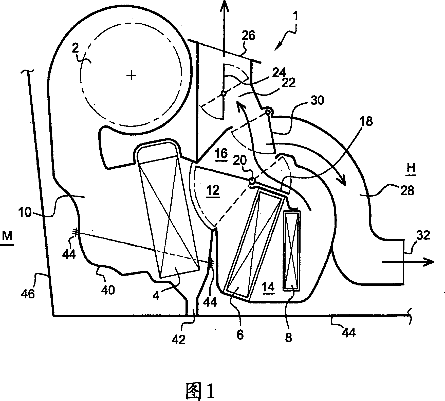
[0022] Reference is first made to FIG. 1 , which shows a cross-sectional view of a heating, ventilation and / or air conditioning unit according to the prior art along a vertical plane oriented in the fore-and-aft direction of the vehicle.

[0023] The heating, ventilation and / or air conditioning unit comprises an enclosure 1 . It includes an engine blower 2 as the main air handling components consisting of an engine and a turbine (not shown), an evaporator 4, a heater 6 and an additional heat source 8 such as a positive temperature coefficient resistor.

[0024] The cabinet 1 may also include airflow filtering means, such as particulate filters, combination filters or photocatalytic filters. These filter elements can be arranged at the air inlet (not shown) upstream of the unit, upstream of the engine fan 2 , or upstream between the engine fan 2 and the evaporator 4 , depending on the direction of air movement.

[0025] The engine blower 2 is arranged on the top of the case 1 ...


PUM


Abstract

The present invention relates to a heating, ventilation and / or air conditioning unit, particularly for a motor vehicle interior, comprising a box ( 1 ) comprising at least one canal ( 10, 28, 96 ) having at least one wall ( 50, 64, 90 ) channelling an air flow in the box ( 1 ). The wall ( 50, 64, 90 ) comprises openings ( 52, 66, 92 ), and at least one sound absorption part ( 54, 60, 70, 72, 74 ) is arranged outside the canal ( 10, 28, 96 ) in contact with the openings ( 52, 66, 92 ).

Description

technical field [0001] The invention relates to a heating, ventilation and / or air conditioning unit. More particularly, it concerns improving the sound insulation of these units. Background technique [0002] Heating, ventilation and / or air conditioning units typically include engine fans, cold and hot heat exchangers such as evaporators, heater / coolers and electric heaters. They also include air flow distribution inside the case. All of these components generate noise from the circulation of air in the channels or through the exchanger, the rotation of the engine-driven engine fan and the movement of the dampers to change the distribution of air flow in the heating, ventilation and / or air conditioning unit. [0003] These dampers are a source of noise, especially when the dampers stop against the walls of the heating, ventilation and / or air conditioning unit, typically causing a rattling sound during their movement. [0004] It has been proposed to reduce this noise poll...

Claims


Application Information

Patent Timeline
IPC IPC(8): F24F13/24B60H1/00
CPCB60H2001/006B60H1/00514
Inventor A·阿尔莫里R·施特勒拉
Owner VALEO SYST THERMIQUES
Learn More