Apparatus and method for accurately converting groove/land polarity on optical medium

一种光学、媒介的技术,应用在光盘的读写装置领域,能够解决无法确定沟/地切换位置等问题

Inactive Publication Date: 2007-05-02
MEDIATEK INC
View PDF2 Cites 0 Cited by
  • Summary
  • Abstract
  • Description
  • Claims
  • Application Information

AI Technical Summary

Problems solved by technology

However, once the physical identification data cannot be decoded from the last three sectors at the end of each track, it means that the mechanism fails, and it cannot determine a precise groove / ground switching position

Method used


Image

  • Apparatus and method for accurately converting groove/land polarity on optical medium
  • Apparatus and method for accurately converting groove/land polarity on optical medium
  • Apparatus and method for accurately converting groove/land polarity on optical medium

Examples


Embodiment Construction

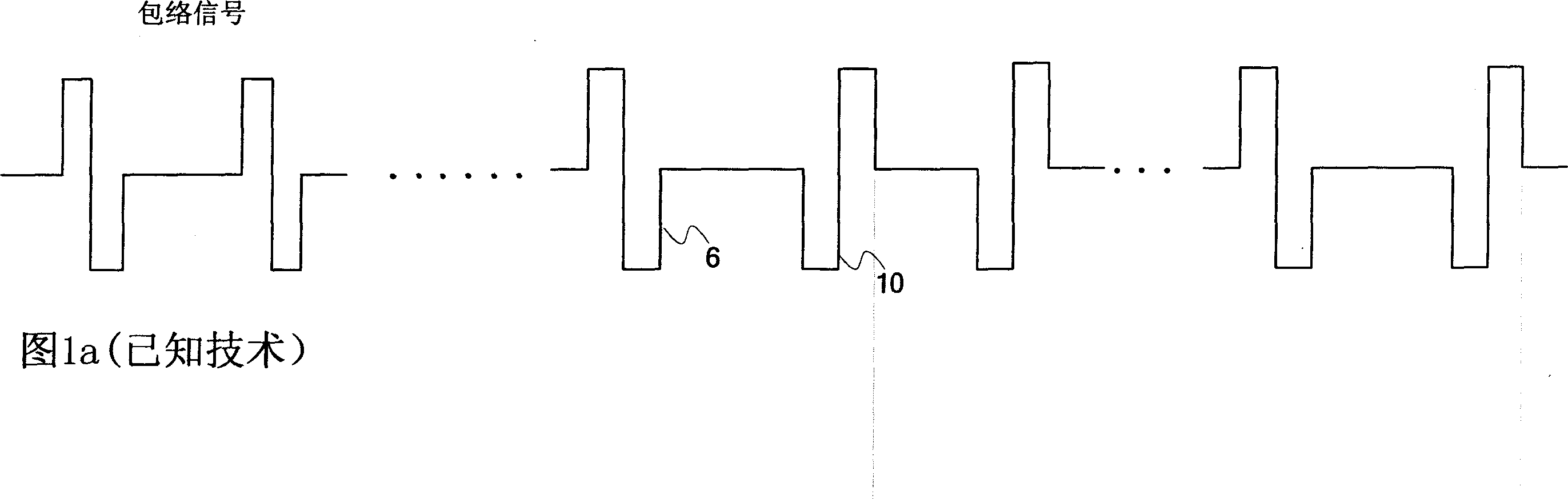
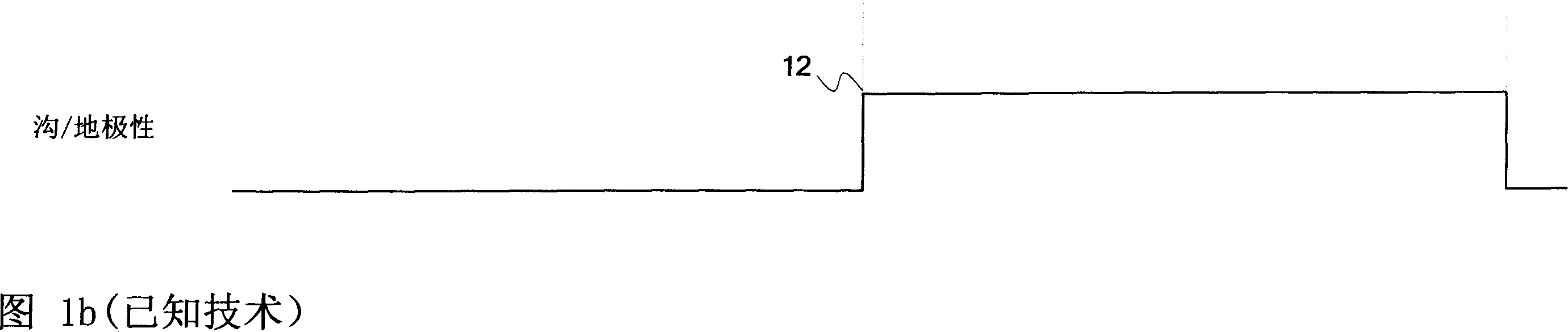
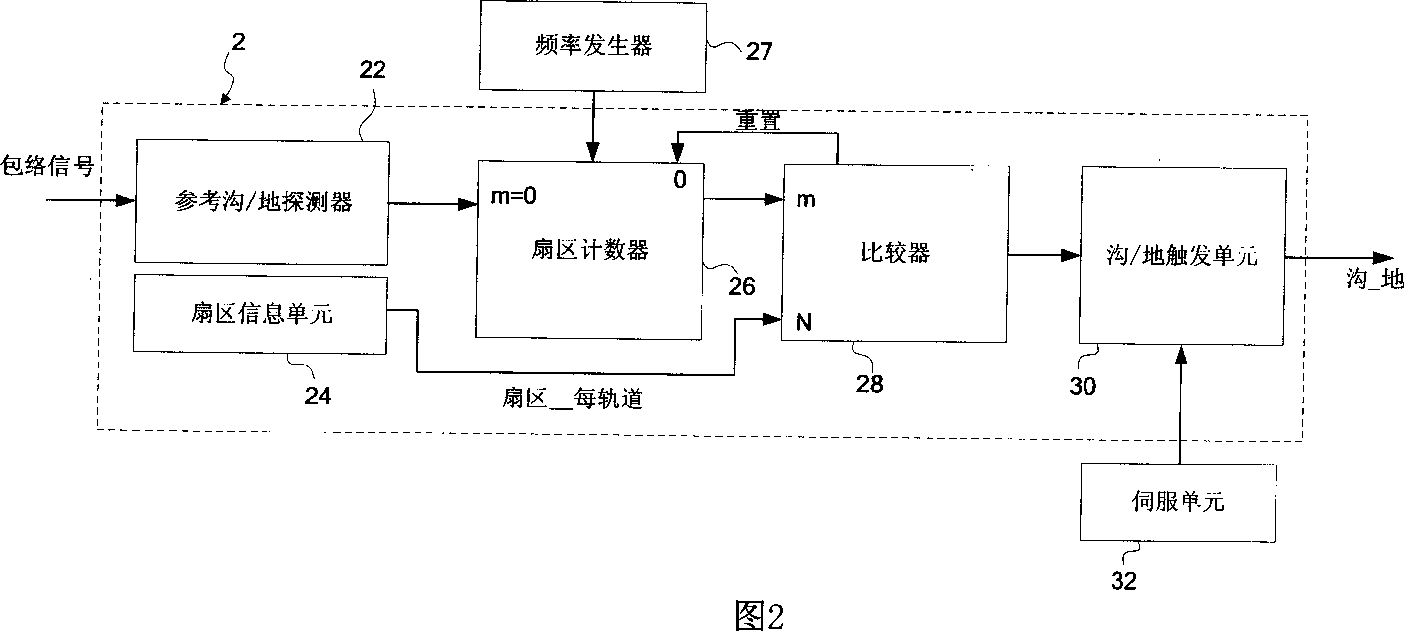
[0037] Please refer to FIG. 2, which is a track polarity switching device 2 according to a first embodiment of the present invention, which can accurately switch its groove for a groove / ground (Groove / Land) track switching on an optical medium (not shown). / ground polarity. The track polarity switching device 2 includes a reference groove / ground detector 22 , a sector information unit 24 , a sector counter 26 , a comparator 28 and a groove / ground switching unit 30 . Based on the polarity switching of an envelope signal (Envelop Signal) shown in FIG. 1 a , the reference groove / ground detector 22 initially searches for a reference groove / ground change point on the optical medium. In another case, by counting the number of periods of the wobble signal (Wobble Signal) to confirm the number of sectors (Sector) in each track (Track), the reference groove / ground change point can also be found. Once the reference trench / ground change point is found, the reference trench / ground detec...


PUM


Abstract

The invention relates to an apparatus for accurately converting groove / land polarity on an optical medium and a method thereof. At present, optical disk data is continuously assigned and recorded in a groove / land track on optical disk surface by a read / write head. The groove / land track is divided into several sectors, each of which includes a first marked data region and an user data region, wherein the first marked region prestores physical mark data for marking a physical position of the first marked region, each sector has an exclusive physical mark data. A servo unit switchs the groove / land polarity of output control for performing reliable data reading / writing when a beam of light of the read / write head scans a switch point of the groove / land track. The object of the invention is to accurately determine the groove / land switch point on the optical disk so as to keep a stable servo control during the reading / writing process. The invention can accurately and real-time determine a next groove / land switch point just by finding a reference groove / land switch point or reading any decoded physical mark data.

Description

technical field [0001] The invention relates to an optical disc reading and writing device and method, in particular to a device and method for accurately switching groove / ground polarity on an optical medium. Background technique [0002] Recently, with the trend of accommodating a large amount of digital content (such as video and audio data), the development of various high-density optical discs (Disk-shaped Optical Medium) is increasing. For one of the optical discs, such as DVD-RW discs, the data is burned in the grooves (Grooves) with a read / write (Recording / Reading) device (Pickup head), which is like forming on the optical disc. In the pit (Pit) on the surface. For another kind of optical disc, such as DVD-RAM (Digital Versatile Disk-Random Access Memory) optical disc, its data is allocated continuously by the read-write head and burned in the groove (Groove) and land (Land) on the surface of the optical disc, which is like Formed in pits of different levels. This...

Claims


Application Information

Patent Timeline
Patent Type & Authority Applications(China)
IPC IPC(8): G11B7/00G11B7/09G11B20/00
CPCG11B7/00718G11B7/0901
Inventor 林孟学
Owner MEDIATEK INC
Why Eureka
Try Eureka