
Rotary saw

A technology of rotation direction and base parts, which is applied in the direction of sawing machine devices, metal sawing equipment, and knives of sawing machine devices. Ease of formation, effect of function improvement

Active Publication Date: 2007-05-09
TENRYU SAW MFG
View PDF1 Cites 7 Cited by
  • Summary
  • Abstract
  • Description
  • Claims
  • Application Information

AI Technical Summary

Problems solved by technology

[0003] For the existing circular saw, because the separate vibration damping plate is fixed by screws and nuts on the inner peripheral side of the base member, the structure becomes complicated and the weight increases at the same time.
In addition, the size of the cut material to be cut is limited

Method used


Image

  • Rotary saw
  • Rotary saw
  • Rotary saw

Examples


Embodiment Construction

[0019] Embodiments of the present invention will be described below with reference to the drawings.

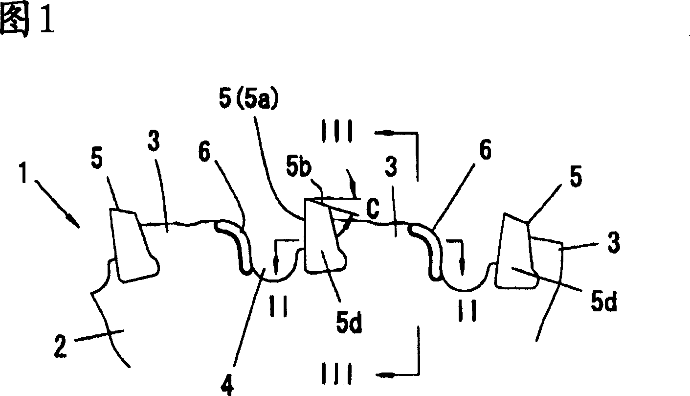
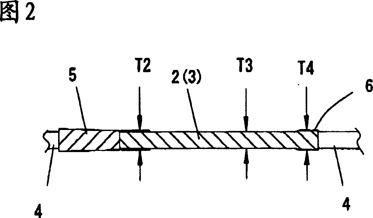
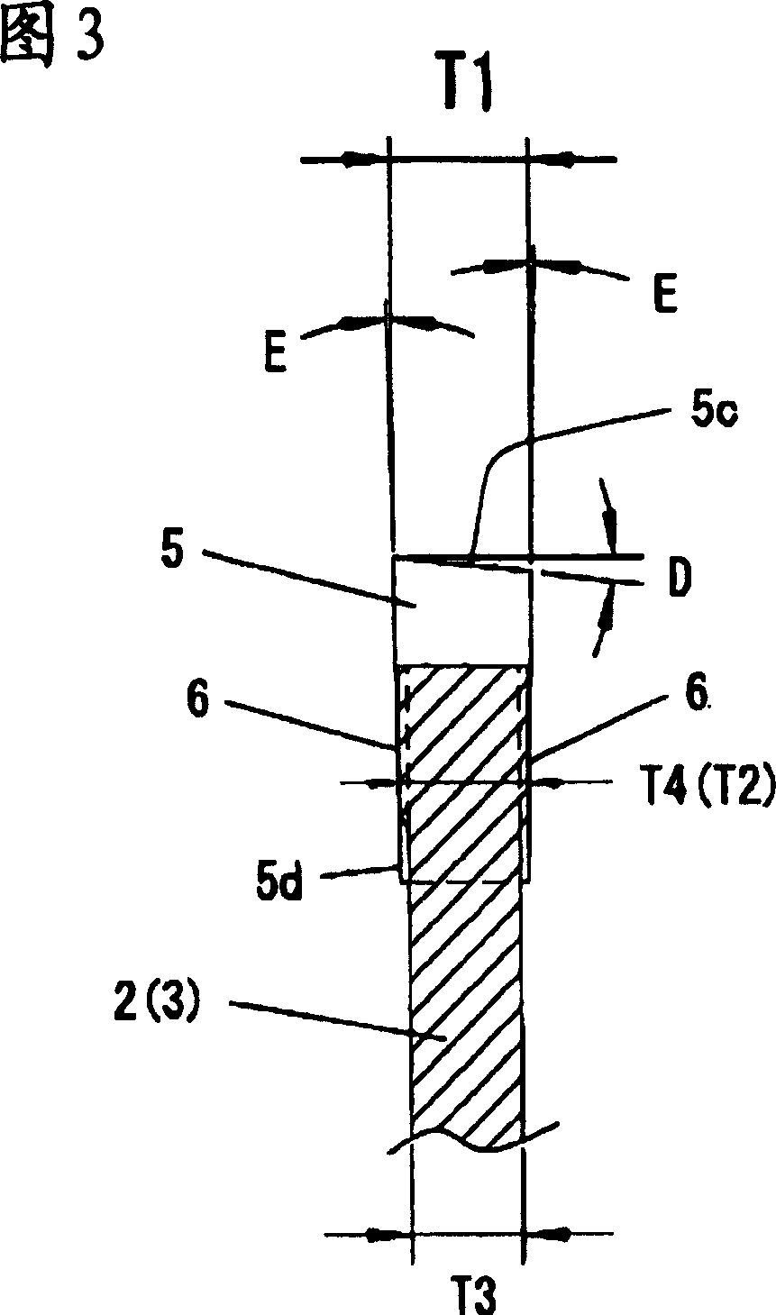
[0020] In the accompanying drawings, Fig. 1 is a partial side view of the first embodiment of the present invention; Fig. 2 is an enlarged side view of the II-II line of Fig. 1; Fig. 3 is an enlarged sectional view of the III-III line of Fig. 1; Fig. 4 is the partial side view of the 2nd embodiment of the present invention; Fig. 5 is the partial side view of the 3rd embodiment of the present invention; Fig. 6 is the partial side view of the 4th embodiment of the present invention; Fig. 7 is Fig. 6 The enlarged cross-sectional view of the VII-VII line;

[0021] Among Fig. 1~3, 1 is the rotary saw that cuts steel; 2 is the base part of rotary saw. The base member 2 is formed of alloy knife steel (JIS standard: SK5, SK6), and in this embodiment, it is formed into a disc shape with an outer diameter of about 185 mm and a reference thickness T3 of about 1.6 mm, and at the same tim...


PUM


Abstract

A rotary saw having a simple structure without increasing weight and capable of reducing lateral swinging is provided. A plurality of blades (5) which has a thickness thicker than the reference thickness (T3) of a base member is separately arranged with intervals along circumferential direction at the outer periphery of the disk-shape base member (2). A projecting portion (6) having a thickness thinner than thickness of the blade and thicker than reference thickness (T3) of the base member (2) is arranged at part of the outer periphery. Furthermore, at front side of rotating direction of each blade is arranged with a concave portion (4) depressing towards a central direction of the base member (2), at inner face of the concave portion (4) is arranged with a projecting portion (6) having a thickness thinner than thickness of the blade and thicker than reference thickness (T3) of the base member (2), the end portion at rear side of rotating direction of the projecting portion (6) contacts the base portion (5d) of the blade (5).

Description

technical field [0001] The present invention relates to a rotary saw for cutting steel materials, wood, ALC (light foam concrete), wood connection (wooden sement), and the like. Background technique [0002] As a prior art, there is a circular saw in which a blade (blade) is fixed on the outer peripheral edge of a base at a predetermined pitch, and a vibration damping plate is fixed on the inner peripheral side of the base with screws and nuts. The anti-vibration plate reduces the vibration and lateral vibration when cutting off. [0003] In the conventional circular saw, since the separate vibration damping plate is fixed by screws and nuts on the inner peripheral side of the base member, the structure becomes complicated and the weight increases at the same time. In addition, the size of the cut material to be cut is limited. [0004] [Patent Document 1] Japanese Patent Laid-Open No. 10-296529 Contents of the invention [0005] The purpose of the present invention is ...

Claims


Application Information

Patent Timeline
Patent Type & Authority Applications(China)
IPC IPC(8): B23D47/00B23D61/04
CPCY10T83/935B23D61/04
Inventor 浅田仁彦
Owner TENRYU SAW MFG
Learn More