Supercharge Your Innovation With Domain-Expert AI Agents!

Magnetic brake for powered window covering

A covering and electric technology, applied in the direction of permanent magnet clutch/brake, electric components, windows/doors, etc.

Active Publication Date: 2007-05-16
SOMFY ACTIVITES SA
View PDF1 Cites 0 Cited by
  • Summary
  • Abstract
  • Description
  • Claims
  • Application Information

AI Technical Summary

Problems solved by technology

It has been noted that the braking magnetic field has a negative effect on the electromagnetic operation of the motor

Method used


Image

  • Magnetic brake for powered window covering
  • Magnetic brake for powered window covering

Examples


Embodiment Construction

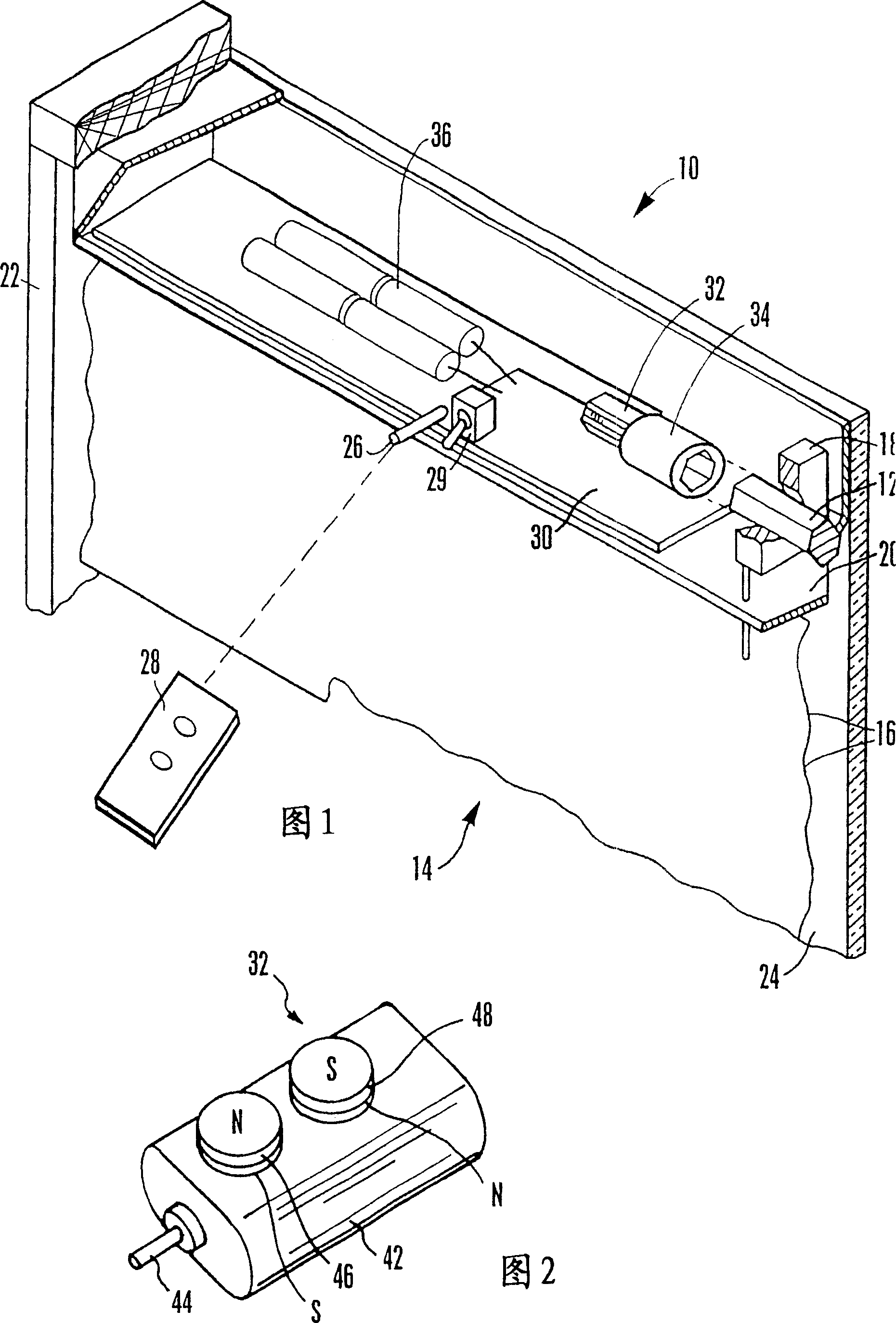
[0016] Referring initially to FIG. 1 , there is shown a motorized window covering generally indicated at 10 including an actuator such as a pivot lever 12 of a window covering 14 such as but not limited to a motorized window covering 14 having a liftable (via Roll up) and lowerable (by rolling down or unfolding) shade 16 shade assembly. As shown, the tilt bar 12 is rotatably mounted in the nose rail 20 of the window covering 14 via spacers 18 .

[0017] While only a rolled up shade is shown, it should be understood that this principle applies to a wide range of window coverings or other objects moved by a motor. For example, the invention is applicable to pleated and honeycomb shades that can be raised and lowered, as well as projection screens, awnings, etc. that can be raised and lowered. Also, although the invention is less required in applications where only slope is required as in slats in horizontal blinds, the invention may also be adapted for use in these systems. Th...


PUM


Abstract

Two braking magnets (46, 48) are attached to the housing of a motor (32) of a motorized component such as a window covering (14), with one magnet north face down and the other magnet south face down. With this structure the motor is braked from turning under the weight of the window covering when deenergized, while during operation the average null value of the braking field results in minimal drag on the motor.

Description

technical field [0001] The present invention generally relates to motorized window coverings, awnings, protective screens, projection screens and the like. Background technique [0002] The present assignee has provided a number of systems for lowering or raising window coverings, or for moving slats of window coverings between open and closed positions, under the control of a hand-held remote control device or other control device . These systems include a motor that is geared to the window covering actuation mechanism. The actuation mechanism moves the window covering when the motor is energized in response to a user command signal. These components are disclosed in US Patent No. 6,433,498, which is hereby incorporated by reference. [0003] The present assignee also provides a system for determining window covering position based on counting motor pulses, and for braking the motor from rotation when the motor is de-energized. By knowing the position of the window cove...

Claims


Application Information

Patent Timeline
IPC IPC(8): E06B9/90H02K7/106E06B9/32H02K49/10
CPCH02K49/10E06B9/90E06B9/32H02K7/106
Inventor 皮埃尔-埃马纽埃尔·卡瓦雷克温斯顿·G·沃尔克
Owner SOMFY ACTIVITES SA
Features
  • R&D
  • Intellectual Property
  • Life Sciences
  • Materials
  • Tech Scout
  • Unparalleled Data Quality
  • Higher Quality Content
  • 60% Fewer Hallucinations
Learn More