X-ray ct method and x-ray ct apparatus

A technology of line projection and line data, applied in the field of X-ray CT, can solve problems such as not being raised, and achieve the effect of enhancing freedom and optimizing radiographic imaging conditions

Inactive Publication Date: 2007-05-30
GE MEDICAL SYST GLOBAL TECH CO LLC
View PDF1 Cites 8 Cited by
  • Summary
  • Abstract
  • Description
  • Claims
  • Application Information

AI Technical Summary

Problems solved by technology

However, there is no proposal for radiographic imaging of multiple organs by diversifying radiographic methods during one irradiation of an X-ray cone beam

Method used


Image

  • X-ray ct method and x-ray ct apparatus
  • X-ray ct method and x-ray ct apparatus
  • X-ray ct method and x-ray ct apparatus

Examples


Embodiment Construction

[0073] Referring to the drawings, the best mode of implementing the X-ray CT method and X-ray CT apparatus according to the present invention will be described below. It should be noted that the present invention is not limited to the best mode.

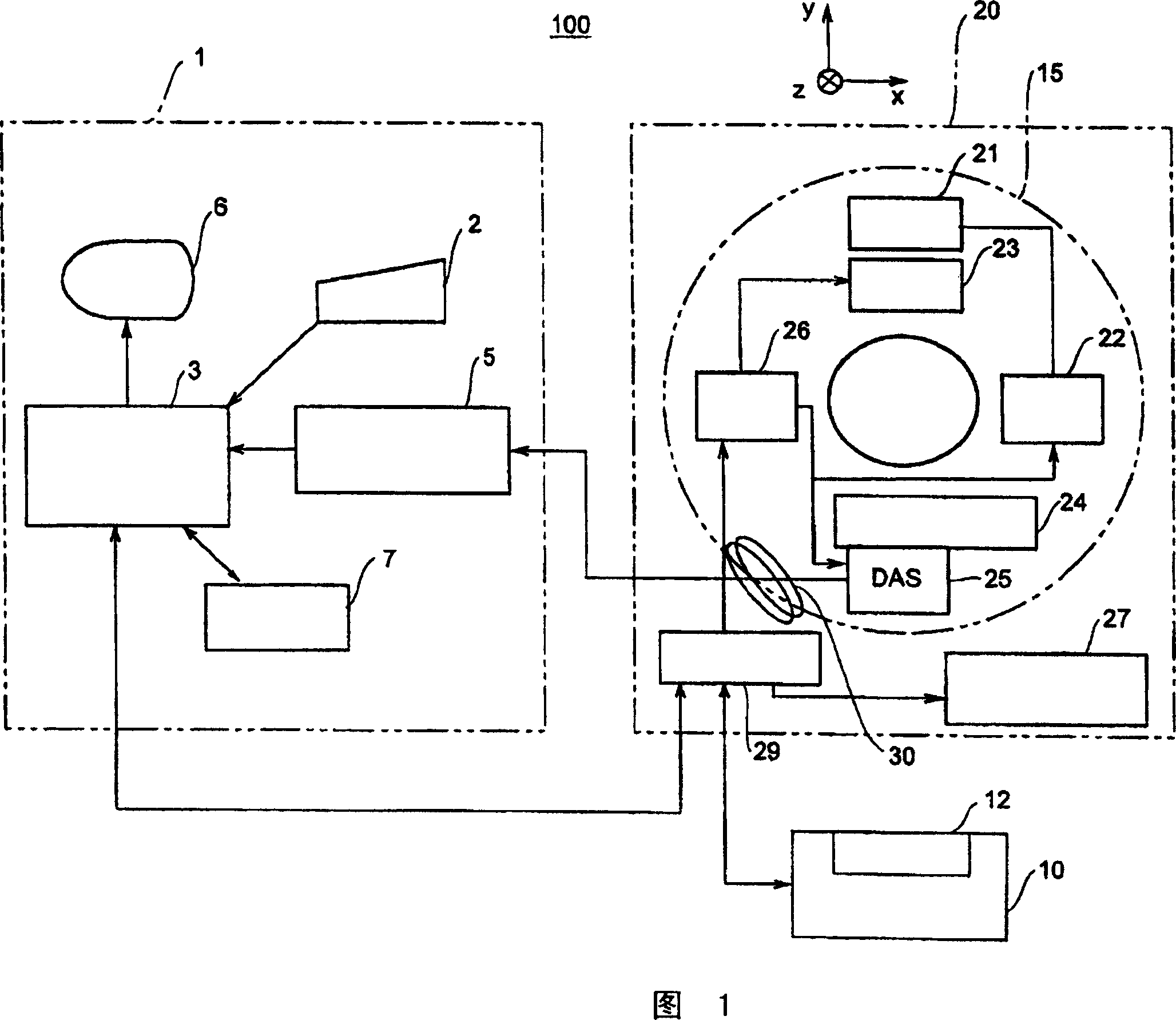
[0074] FIG. 1 is a block diagram showing an overall configuration of an X-ray CT apparatus according to an embodiment of the present invention. The X-ray CT apparatus 100 includes an operator console 1 , a radiation imaging platform 10 and a scanning gantry 20 .

[0075] The operator console 1 includes: an input device 2, which receives input from the operator; a central processing unit 3, which includes image reconstruction devices for performing pre-processing, image reconstruction, and post-processing; a data collection buffer 5, composed of a scanning table The X-ray detector data acquired by the frame 20 is collected therein; the monitor 6, which is an image display device, on which a tomographic image reconstructed based on th...


PUM


Abstract

In an X-ray CT apparatus including an X-ray area detector that has a matrix structure and is represented by a multi-array X-ray detector or a flat-panel X-ray detector, radiographic conditions (protocols) for imaging of each position represented by a z-coordinate are optimized in relation to an X-ray cone beam that spreads in a z direction. A slice thickness of a tomographic image is freely controlled in the z direction using a z filter during a conventional scan or a cine scan. For each tomographic image, a reconstruction function, an image filter, a scan field, a tomographic-image tilt angle, and a position of a tomographic image are freely adjusted or independently designated for scanning of each position in the z direction. Thus, a tomographic image is reconstructed. Moreover, the position of a beam formation X-ray filter in the z direction is shifted in order to optimize a patient dose that depends on the size of the scan field, and X-ray quality.

Description

technical field [0001] The present invention relates to an X-ray CT method and an X-ray CT apparatus in which radiographic conditions are specified for a conventional scan or a cine scan. Background technique [0002] In an X-ray CT apparatus including an X-ray area detector typified by a multi-array X-ray detector or a flat-panel X-ray detector, only one set of radioactive Imaging conditions (protocol), X-rays are irradiated once rotationally for the conventional scan, and the photographic scan keeps the subject stable at a scan position. Furthermore, the freedom to specify the radiographic conditions for radiation of one rotation of the X-ray cone beam is limited. This raises the question of optimization of the radiographic conditions. [0003] Fig. 20 shows X-ray data acquisition components included in a conventional X-ray CT apparatus. The X-ray data acquisition assembly includes an X-ray tube 41 for generating X-rays, a collimator 43 for controlling the X-ray scannin...

Claims


Application Information

Patent Timeline
Patent Type & Authority Applications(China)
IPC IPC(8): A61B6/03
CPCA61B6/488A61B6/469A61B6/4085A61B6/027A61B6/032A61B6/03
Inventor 西出明彦今井靖浩
Owner GE MEDICAL SYST GLOBAL TECH CO LLC
Why Eureka
Try Eureka