Equipment for realizing dual-energy CT by using flying focal spot mode and method thereof

A technology of flying focus and equipment, which is applied in the field of medical imaging, can solve the problems that it is difficult to realize the combination of high and low KV scanning mode and flying focus scanning mode, achieve fast switching speed, reduce the demand for slip ring bandwidth, and reduce costs Effect

Pending Publication Date: 2019-11-22
ZHONGSHAN MINFOUND MEDICAL EQUIP CO LTD
View PDF14 Cites 5 Cited by
  • Summary
  • Abstract
  • Description
  • Claims
  • Application Information

AI Technical Summary

Problems solved by technology

In cardiac scanning, it is almost difficult to realize the combination of high and low KV scanning mode and femto-focus scanning mode in the existing technology

Method used


Image

  • Equipment for realizing dual-energy CT by using flying focal spot mode and method thereof
  • Equipment for realizing dual-energy CT by using flying focal spot mode and method thereof
  • Equipment for realizing dual-energy CT by using flying focal spot mode and method thereof

Examples


Embodiment 1

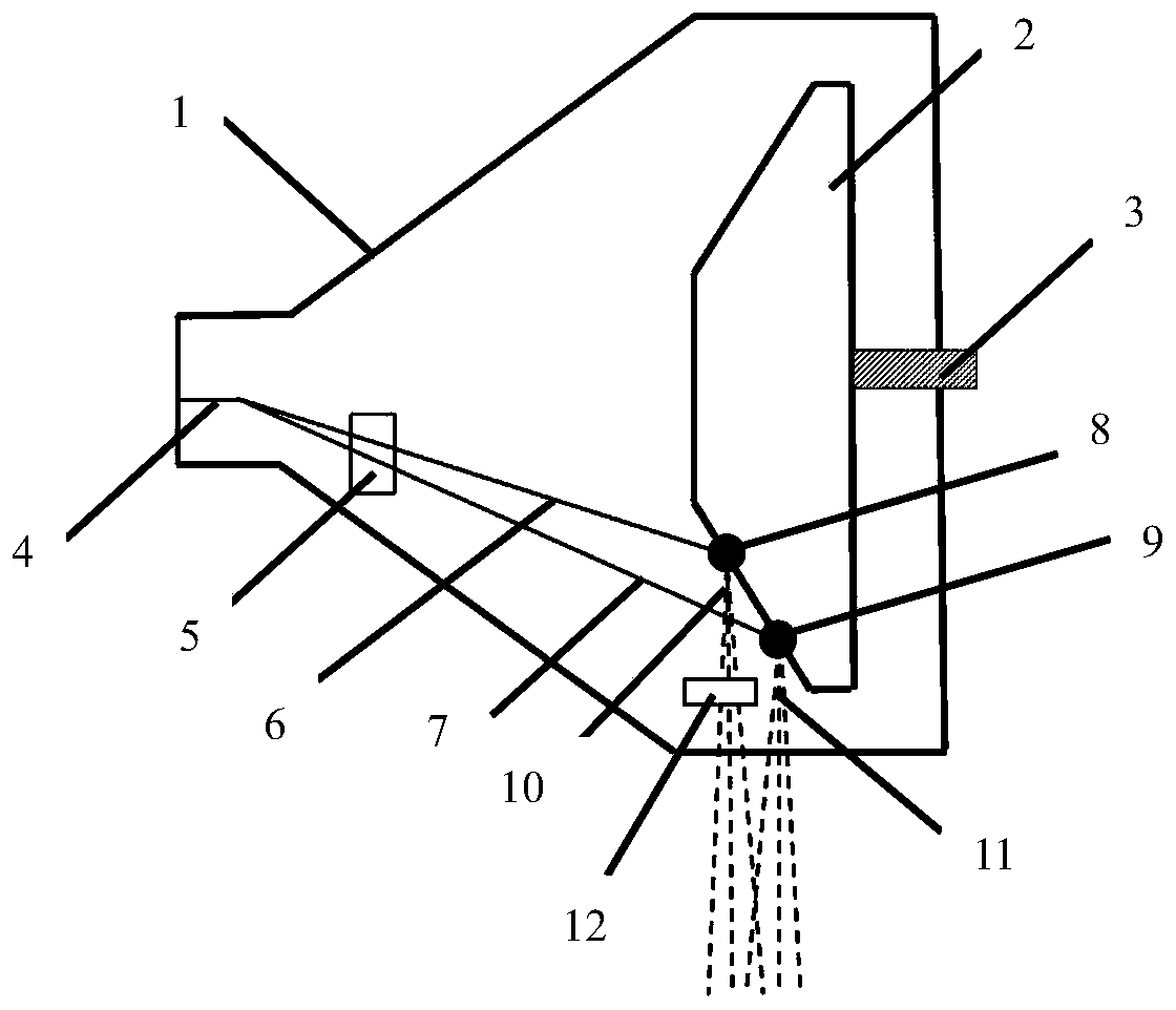
[0032] A device for realizing dual-energy CT by using a flying focus method, including an X-ray tube, a beam limiter, and a detector; wherein, the X-ray tube includes an X-ray filter 12, a casing 1, a cathode filament 4, and an anode target 2 and an electron beam position control device 5, the X-ray filter is arranged on the first X-ray beam 10 in the X-ray tube, such as figure 1 shown.

[0033] X-ray filters can be metal materials such as tin, molybdenum, copper, aluminum, platinum, zinc and their alloys, or ceramic materials that can absorb low-energy X-rays.

[0034] The method of using the device includes the following steps:

[0035] S1. Scan after installing the X-ray tube and performing mechanical position alignment;

[0036] S2. During the scanning process, by controlling the electron beam position control device, the focus position is switched instantaneously at high frequency; it is realized by deflecting and focusing the electron beam emitted by the cathode throug...

Embodiment 2

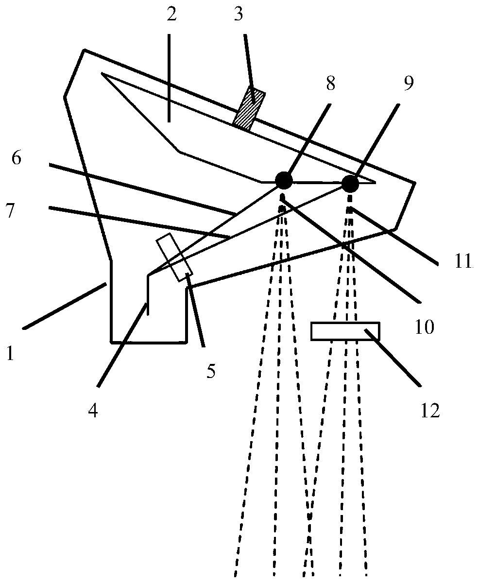
[0042]Compared with Embodiment 1, the positions of the first optical focus 8 and the second optical focus 9 are far enough in this embodiment, and at this time, the X-ray filter 12 is arranged on the second X-ray beam 11 outside the X-ray tube, which can also be Change the X-ray energy spectrum. Such as figure 2 shown.

Embodiment 3

[0044] Compared with Embodiment 1, in this embodiment, a speed reducer 13 is adopted to replace the X-ray filter 12, and the speed reducer 13 is arranged on the second electron beam 7 in the X-ray tube, as image 3 shown. The energy of the second electron beam 7 and the first electron beam 6 passing through the speed reducer 13 is different, so the energy distribution of the X-ray spectrum generated at the first optical focus 8 and the second optical focus 9 will be different, so as to change the energy spectrum the goal of. The decelerator 13 may be a reverse electric field electrode, which decelerates electrons through a reverse electric field.

[0045] In other preferred solutions, the speed reducer 13 can also be a device consisting of two equipotential electrodes, which reduces the energy of the electron beam by reducing the acceleration distance of the electron beam. On the path of the electrons, the reverse electric field formed by the two electrodes will give the ele...


PUM


Abstract

The invention provides equipment for realizing dual-energy CT by using a flying focal spot mode. The equipment includes an X-ray tube, a beam limiter and a detector. The X-ray tube further includes ahousing, a cathode filament, an anode target, an electron beam positioner and an X-ray filter; the X-ray filter is arranged on any X-ray beam inside or outside the X-ray tube. The equipment can simultaneously perform the Z-direction flying focal spot and dual-energy CT scanning, and the sampling rate only needs to reach the rate when the normal Z-direction flying focal spot is used, which greatlyreduces the demand for slip ring bandwidth when the dual energy and the flying focal spot are applied simultaneously. And the cost is reduced. By a magnetic field or an electric field for switching the optical focus position, the switching speed is very fast and can reach or exceed the speed of a traditional energy spectrum CT high and low pressure switching.

Description

technical field [0001] The invention belongs to the technical field of medical imaging, and in particular relates to a CT detector method and equipment. Background technique [0002] The main components of the third-generation CT system include Tube (ball tube), Collimator (beam limiter), and Detector (detector). The X-ray tube emits X-rays, which are limited by a beam limiter to form a cone-shaped beam. The cone-shaped light beam is irradiated on the detector and converted into an electrical signal by the detector, and then converted into digital information by the data acquisition and conversion unit and stored in the image processing system. The image processing system generates images and displays them on the monitor through a series of correction algorithms and image reconstruction algorithms. In terms of cost and technology maturity, mainstream detectors use many detector modules arranged on an arc or polygonal surface to form the entire detector. A matrix formed by...

Claims


Application Information

Patent Timeline
Patent Type & Authority Applications(China)
IPC IPC(8): A61B6/03
CPCA61B6/032A61B6/4208A61B6/4241A61B6/4064A61B6/482
Inventor 王斌王瑶法侯晓文
Owner ZHONGSHAN MINFOUND MEDICAL EQUIP CO LTD
Why Eureka
Try Eureka