Smart linear pulsed laser diode driver, and method

a laser diode and linear pulse technology, applied in semiconductor lasers, process and machine control, instruments, etc., can solve the problems of inefficient and dispersible, design to be inefficient and limited, and difficulty in maintaining regulation in power supply, so as to achieve greater reliability, reduce power consumption, and reduce power consumption.

Active Publication Date: 2011-04-14
ANALOG MODULES
View PDF12 Cites 104 Cited by
  • Summary
  • Abstract
  • Description
  • Claims
  • Application Information

AI Technical Summary

Benefits of technology

[0016]Generally, the invention is directed to a technique for automatically minimizing the above-referenced losses, thereby allowing for higher efficiency, smaller size, and greater reliability.

Problems solved by technology

However, this can be inefficient and dissipative because a storage capacitor bank needs to be charged to a voltage substantially higher than the laser diode voltage requirement.
There is also a difficulty in maintaining regulation in a power supply over the range of pulse current draw required, zero to maximum diode current.
This dissipation causes this design to be inefficient and limited by the safe forward operating conditions of the control device.

Method used


Image

  • Smart linear pulsed laser diode driver, and method
  • Smart linear pulsed laser diode driver, and method
  • Smart linear pulsed laser diode driver, and method

Examples


Embodiment Construction

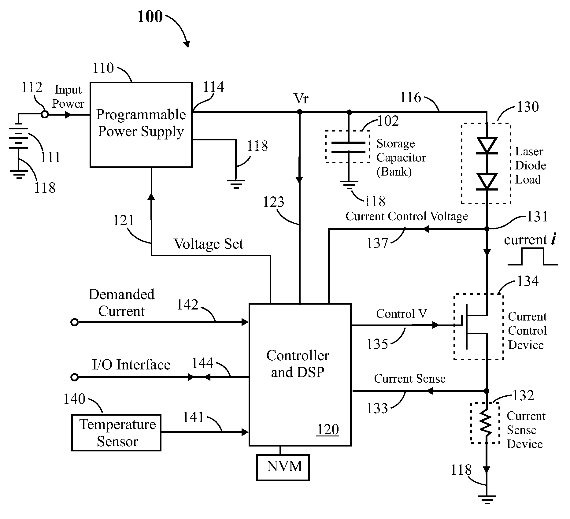
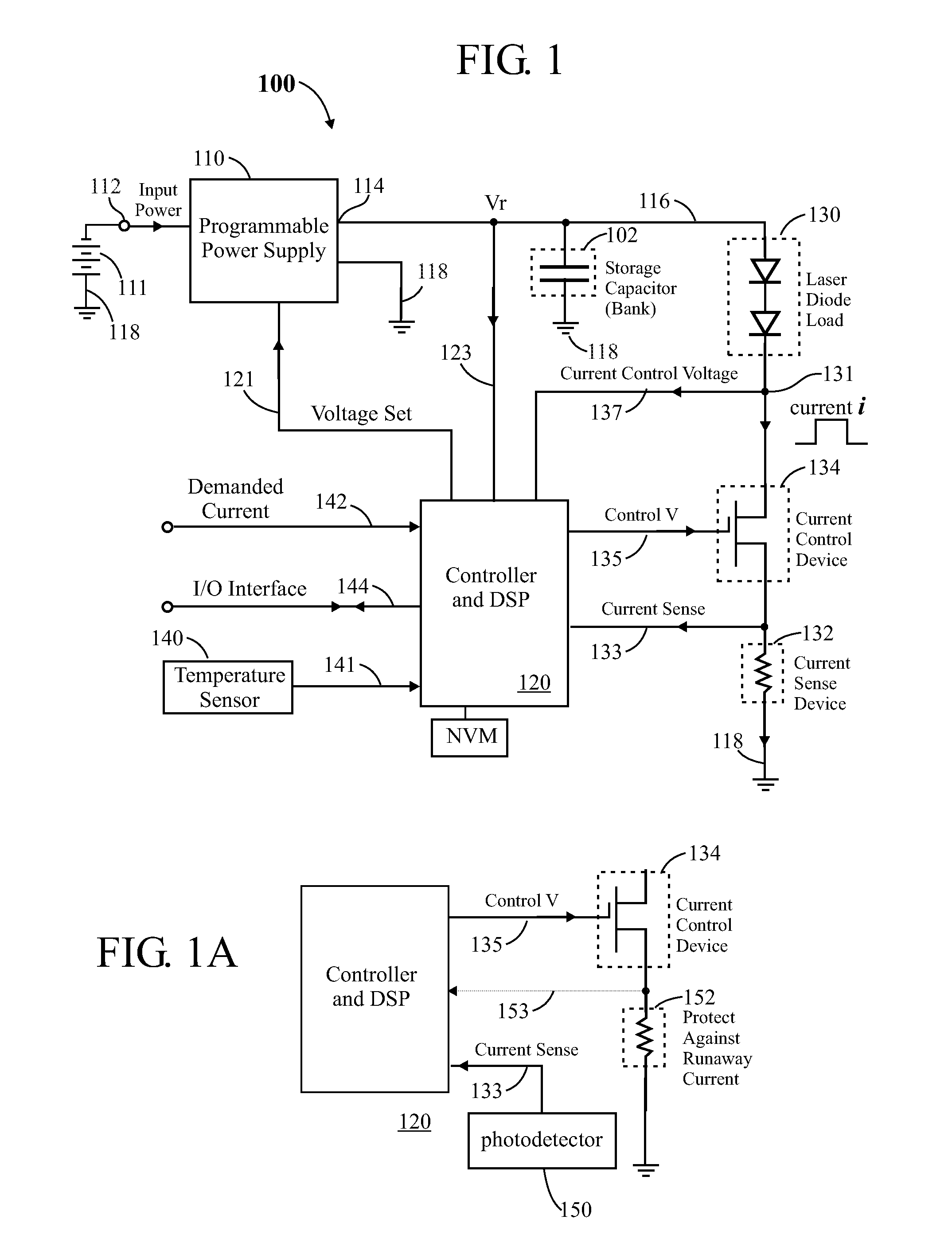
[0043]Conventional electronic components may be labeled with conventional schematic-style references comprising a letter (such as A, C, Q, R) indicating the type of electronic component (such as amplifier, capacitor, transistor, resistor, respectively) followed by a number indicating the iteration of that element (such as “1” meaning a first of typically several of a given type of electronic component). Components such as resistors and capacitors typically have two terminals, which may be referred to herein as “ends”. In some instances, “signals” are referred to, and reference numerals may point to lines that carry said signals. In the schematic diagrams, the various electronic components are connected to one another, as shown. Usually, lines in a schematic diagram which cross over one another and there is a dot at the intersection of the two lines are connected with one another, else (if there is no dot at the intersection) they are typically not connected with one another.

[0044]In...


PUM


Abstract

In a pulsed laser diode driver an energy storage capacitor is continuously being charged to a supply voltage Vr. When a pulse is initiated, energy stored in the capacitor is delivered to the laser diode load. The capacitor voltage Vd at the end of a pulse is used to control Vr to ensure that Vd is maintained above a minimum voltage Vm required to ensure operation of a current control device (such as FET) just above saturation. Test pulses (such as with attenuated currents or reduced pulsewidth) may be fired to determine an initial optimum value for Vr. After a test pulse, a slightly high estimate for Vr may be used and may be iterated (incremented) down to an optimum value Vm during a firing burst. A digital processor may be used to calculate and store data to optimize the performance. Various embodiments are disclosed.

Description

CROSS-REFERENCE TO RELATED APPLICATIONS[0001]This is a non-provisional filing of provisional No. 61 / 250,065 filed Oct. 9, 2009.TECHNICAL FIELD OF THE INVENTION[0002]The invention relates generally to current drivers, more particularly pulsed or variable waveform diode (such as laser or LED) drivers and methods of operation.BACKGROUND OF THE INVENTION[0003]A pulsed current source such as the Analog Modules Model 771 or 778 laser diode drivers may be used to drive a single or stack of laser or light emitting diodes. However, this can be inefficient and dissipative because a storage capacitor bank needs to be charged to a voltage substantially higher than the laser diode voltage requirement. Nevertheless, drawing the laser current from a storage capacitor bank rather than from a power supply and filter may be beneficial because a power supply would have to be rated at a large power to supply the diode current. There is also a difficulty in maintaining regulation in a power supply over ...

Claims


Application Information

Patent Timeline
Patent Type & Authority Applications(United States)
IPC IPC(8): H01S3/00H05B41/36
CPCH01S5/0428H05B33/0818Y02B20/347H05B33/0851H05B33/0854H05B33/0824H05B45/44Y02B20/30H05B45/18H05B45/385H05B45/375H05B45/38
Inventor CRAWFORD, IAN D.HARWICK, JOHN A.AYRES, TIMOTHY M.
Owner ANALOG MODULES
Why Eureka
Try Eureka