Adaptive X-ray filter for changing local intensity of X-ray radiation

一种X射线、自适应的技术,应用在用于放射诊断的仪器、辐射/粒子处理、应用等方向,能够解决成本昂贵、耗费空间等问题

Inactive Publication Date: 2013-11-13
SIEMENS AG
View PDF7 Cites 5 Cited by
  • Summary
  • Abstract
  • Description
  • Claims
  • Application Information

AI Technical Summary

Problems solved by technology

In this case, the contour diaphragm and the prefilter are either inserted manually into the accessory rail of the collimator (Tiefenblende) or processed by means of an expensive and space-consuming electric drive

Method used


Image

  • Adaptive X-ray filter for changing local intensity of X-ray radiation
  • Adaptive X-ray filter for changing local intensity of X-ray radiation
  • Adaptive X-ray filter for changing local intensity of X-ray radiation

Examples


Embodiment Construction

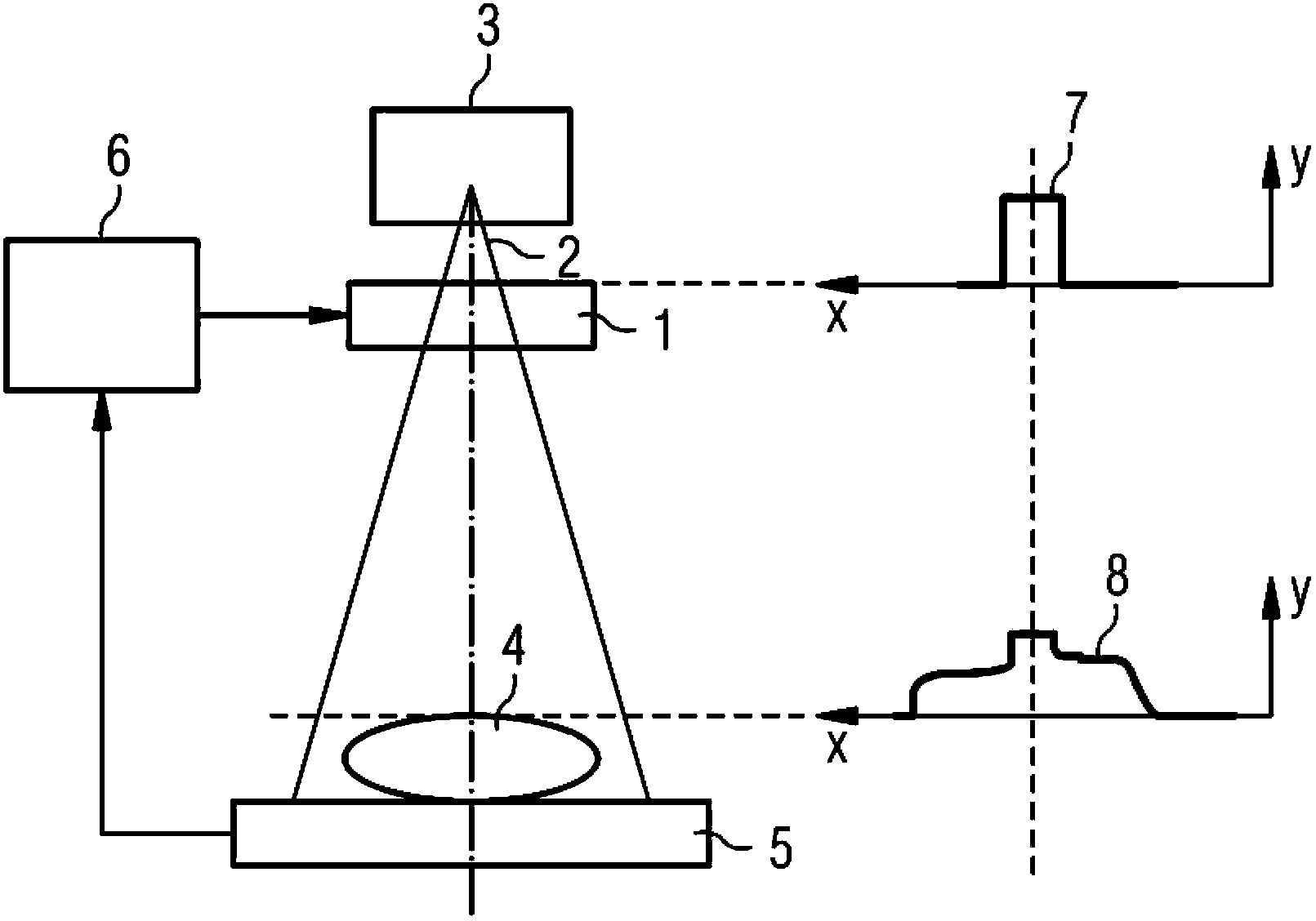
[0020] figure 1 The functional principle of the adaptive X-ray filter is shown. A position-dependent attenuation of the x-ray radiation 2 is produced by the adaptive x-ray filter 1 . X-ray radiation 2 is generated by an X-ray source 3 , first passes through an adaptive X-ray filter according to the invention, then passes through a patient 4 , and is finally detected by an X-ray detector 5 . The local attenuation of the x-rays is controlled by means of the control unit 6 via the adaptive x-ray filter 1 .

[0021] exist figure 1 The intensity profile 7 of the x-ray radiation 2 upstream of the adaptive filter 1 is schematically shown at the top right. Intensity y is shown above the x-axis illustrating position. An almost steady distribution of the intensity y can be seen. exist figure 1 The lower right shows the intensity profile 8 of the x-ray radiation 2 after passing through the adaptive x-ray filter 1. The change of the local intensity y caused by the adaptive x-ray fi...


PUM


Abstract

The adaptive X-ray filter (1) has a primary chamber that is provided with magneto-rheological or electro-rheological liquid. A secondary chamber is provided with X-ray radiation-absorbing liquid. A flexible membrane is provided to separate the primary chamber from the secondary chamber. The film thickness ratio of the liquids is variable. A heating device is located to heat the X-ray radiation-absorbing liquid. The X-ray radiation-absorbing liquid is a liquid metal.

Description

technical field [0001] The invention relates to an adaptive X-ray filter for varying the local intensity of X-ray radiation, having a first cavity, a second cavity and a flexible partition separating the first cavity from the second cavity The layer thickness ratio of the first liquid and the second liquid can be changed through the partition. Background technique [0002] During examinations with the aid of x-ray beams, it often happens that the patient or his organs have a significantly different absorption behavior with respect to the applied x-ray radiation in the region to be examined. For example, when taking a chest shot, in the mediastinum (that is, in the area before the lung lobes) there is a lot of attenuation due to the organs present there, while in the area of ​​the lung lobes themselves there is very little attenuation. Both in order to obtain effective recordings and to treat the patient specifically, it is expedient to adjust the applied dose in a region-de...

Claims


Application Information

Patent Timeline
Patent Type & Authority Applications(China)
IPC IPC(8): G21K1/10A61B6/00
CPCG21K1/10A61B6/4035
Inventor P.伯恩哈特H.利格尔R.F.舒尔茨
Owner SIEMENS AG
Why Eureka
Try Eureka