Supercharge Your Innovation With Domain-Expert AI Agents!

Rotary casing roll

A technology of rotating shells and drums, used in manufacturing tools, calenders, papermaking, etc., can solve the problems of component retention, pad instability, accidental contact of shells, etc., and achieve the effect of improving stability

Inactive Publication Date: 2007-06-20
CLECIM SAS
View PDF2 Cites 2 Cited by
  • Summary
  • Abstract
  • Description
  • Claims
  • Application Information

AI Technical Summary

Problems solved by technology

However, it has been observed that, especially for rolling, various accidents that may occur during use have the risk of destabilizing the block, as well as the risk of contact with the Risk of accidental contact with the housing
As a result, it is sometimes difficult to keep components at the required level

Method used


Image

  • Rotary casing roll
  • Rotary casing roll
  • Rotary casing roll

Examples


Embodiment Construction

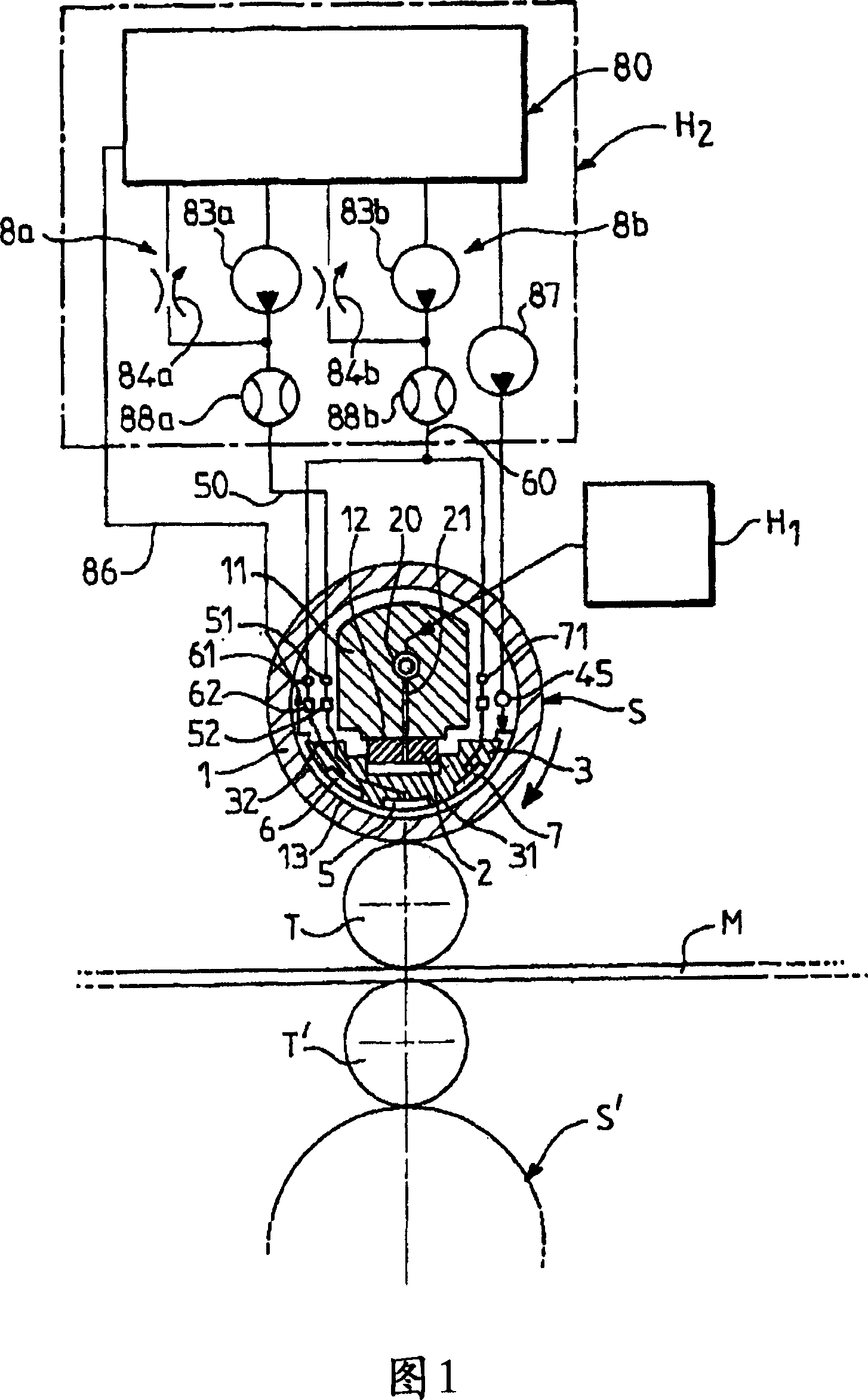
[0040] [40] As shown in Fig. 1 in transverse section as an example, a four-high rolling mill includes two work rolls T, T', between which a rolled product M passes, said work rolls T, T' being respectively on opposite sides of the product Supported on two support rollers S, S' between which a fastening force is exerted along a support plane P passing substantially by the axis of the drum.

[0041] [41] At least one of the supporting rollers, for example the upper supporting roller S, consists of a tubular casing 1 which is rotatably mounted at its ends on a supporting beam 11 via abutments A, A' shown in FIG. 4 , the support beams 11 extend transversely to the rolling direction inside the tubular housing 1 , and the abutments A, A' define an axis of rotation x'x of the housing.

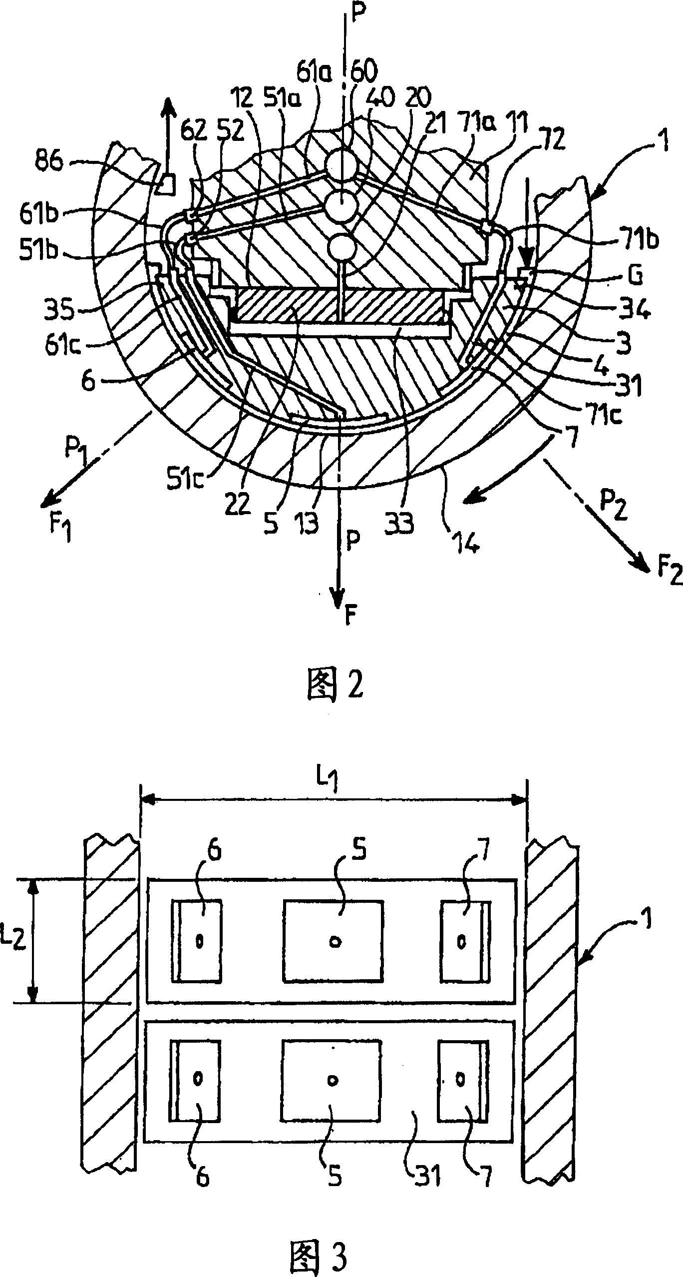
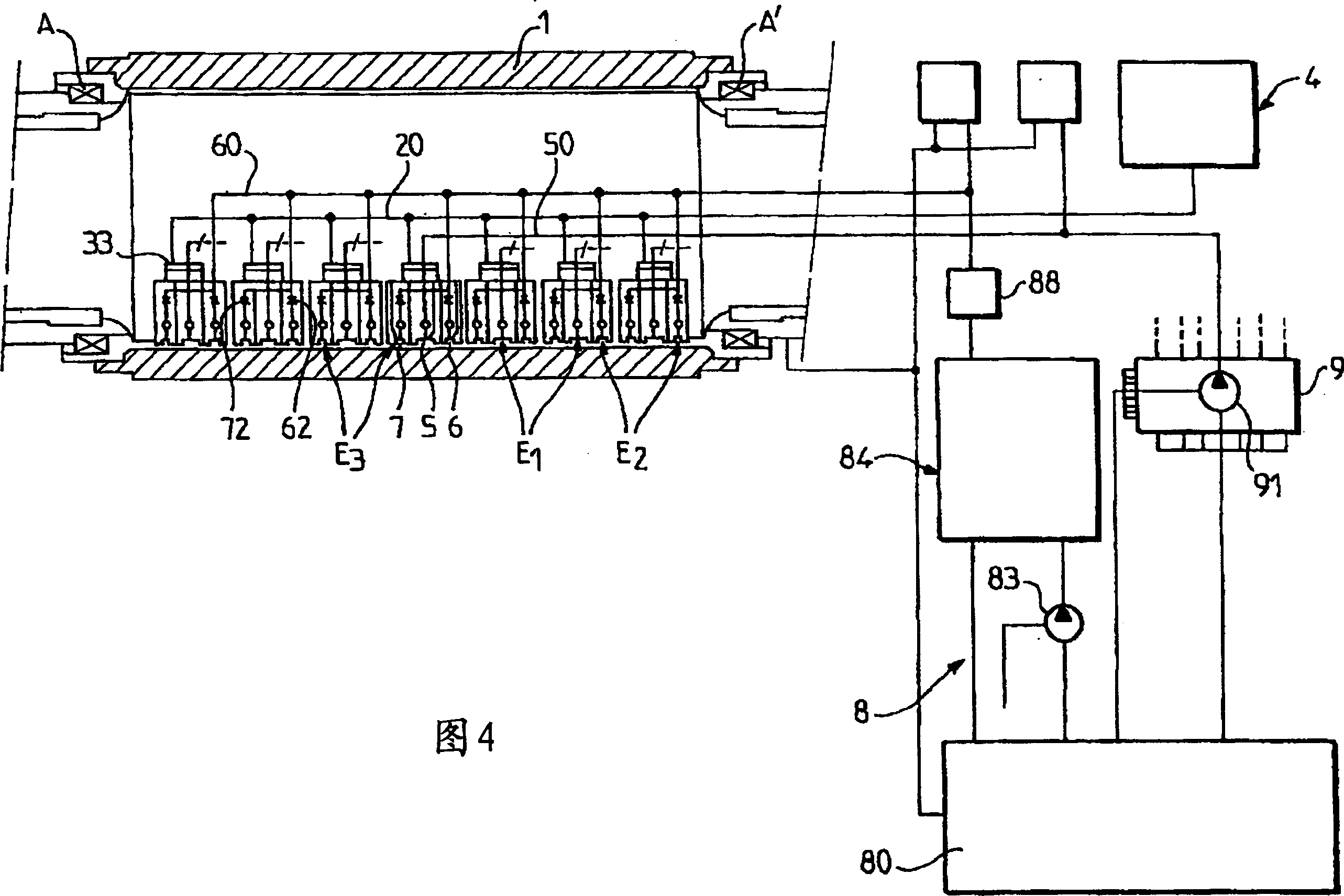
[0042] [42] As shown in Fig. 4, the tubular casing 1 is supported on the beam 11 by a plurality of retaining pads 3 distributed over its entire length and interposed between the between the cylindric...


PUM


Abstract

A rotary casing milling roll with a tubular casing (1) rotationally mounted on a plurality of pads (3) retaining said casing (1), and generating a hydrodynamic bearing effect by injecting a lubricant between the bearing surface (31) of the pad (3) and the inner surface (13) of the casing (1). According to the invention, the bearing surface (31) of each pad is provided with three hydrostatic pockets, a central pocket (5) and an upstream (7) and downstream (6) side pocket respectively, which receive said fluid under a pressure sufficient to produce an additional fluid flow and localised pressure increase in the driven film (4) so as to expand, in an upstream and downstream direction, the hydrodynamic bearing angular sector (4) while maintaining, over the entire length thereof, the fluid flow required to obtain the desired bearing effect.

Description

technical field [0001] [01] The present invention relates to a rotary shell drum consisting of a cylindrical tubular shell rotatably mounted around an elongated support, supported on said support by a set of holders, particularly suitable for use in a A back-up roll is implemented on metal strip mills, especially steel strip mills. Background technique [0002] [02] For some time, first, in papermaking, and then, more recently, in metal strip mills, the use of rotating shelled cylinders, comprising a long beam-shaped stationary support shaft, has been proposed , said support shaft is surrounded by a tubular housing rotatably mounted about a support, defining an axis of rotation transverse to the rolling axis, and supported on said beam by a series of holders, one Distributed on the other side over the entire length of the beam and centered on an axial support plane passing through the axis of the drum and a support generatrix and corresponding to when the The roller is the...

Claims


Application Information

Patent Timeline
Patent Type & Authority Applications(China)
IPC IPC(8): B21B13/14D21G1/02F16C13/00
CPCF16C13/028D21G1/022B21B27/055
Inventor 让-保罗·富尔埃里克·帕拉屈埃洛斯王骏飞陈守群
Owner CLECIM SAS
Features
  • R&D
  • Intellectual Property
  • Life Sciences
  • Materials
  • Tech Scout
  • Unparalleled Data Quality
  • Higher Quality Content
  • 60% Fewer Hallucinations
Learn More