Charging device

a charging device and charging technology, applied in the direction of electric vehicles, transportation and packaging, battery arrangement for several simultaneous batteries, etc., can solve the problems and achieve the effect of time-consuming and labor-intensive user's removal of batteries and convenient inserting and taking out batteries

Active Publication Date: 2018-07-17
GETAC TECH CORP
View PDF10 Cites 1 Cited by
  • Summary
  • Abstract
  • Description
  • Claims
  • Application Information

AI Technical Summary

Benefits of technology

[0004]To allow a charging terminal of a battery to be fully and firmly connected to a charging terminal of a conventional charger, the conventional charger is designed in a manner that a clamping structure disposed inside a slot can generate a large clamping force or a fixing mechanism is optionally disposed inside the slot. However, the aforesaid advantage is achieved at the expense of ease of use. For instance, it is time-consuming and laborious for the user to take out the battery, as the user must take out the battery by both hands, with one hand pressing on the charger and the other hand generating a pulling force for taking the battery out. Alternatively, the user has to perform a specific loosening operation on the fixing mechanism in order to take the battery out. In view of this, the present invention provides a charging device whereby not only can a battery be firmly inserted into the charging device but it is easy to insert and take out the battery.
[0013]In conclusion, the present invention provides a charging device which comprises a charging base with a receiving chamber and a hook portion such that a user can put a battery in the receiving chamber easily to allow the battery to be fully and firmly engaged with the charging base and the hook portion, thereby preventing power interruption which might otherwise occur because of loose contact or poor contact. To take out the battery, the user rotates the battery slightly about a fulcrum to thereby detach the battery from the hook portion and take out the battery freely. A point of the bottom of the receiving chamber is in contact with a base angle of the battery and functions as the fulcrum. Accordingly, it is convenient, quick and easy for the user to operate the charging device of the present invention.

Problems solved by technology

For instance, it is time-consuming and laborious for the user to take out the battery, as the user must take out the battery by both hands, with one hand pressing on the charger and the other hand generating a pulling force for taking the battery out.

Method used


Image

  • Charging device
  • Charging device
  • Charging device

Examples


Embodiment Construction

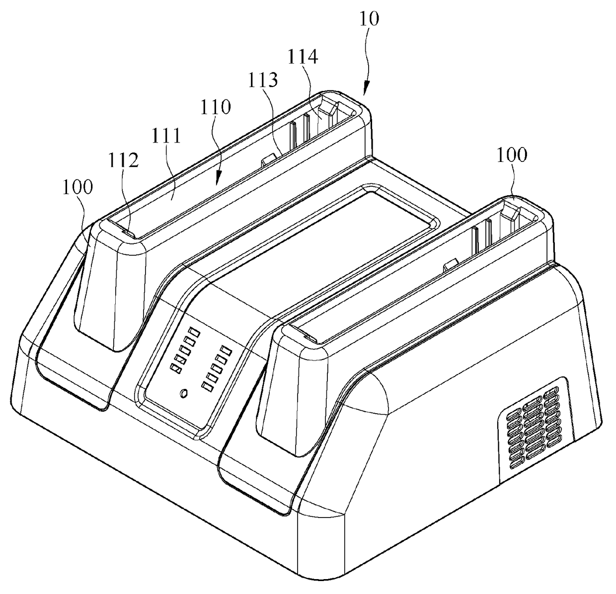
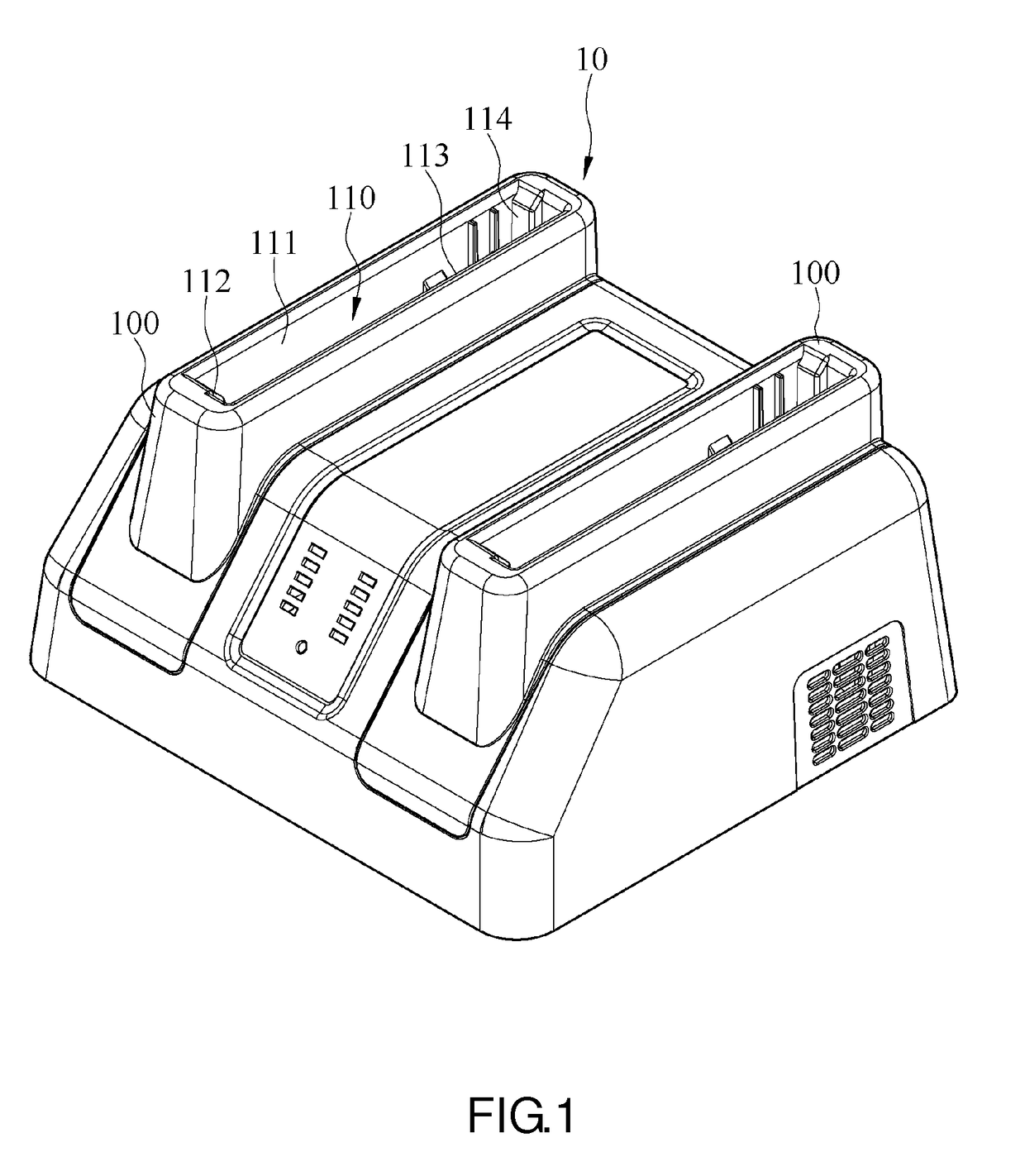
[0024]Referring to FIG. 1, there is shown a schematic view of a charging device 10 according to an embodiment of the present invention. In this embodiment, the charging device 10 has two charging bases 100, but the present invention is not limited thereto. In another embodiment, the charging device has one or at least three charging bases.

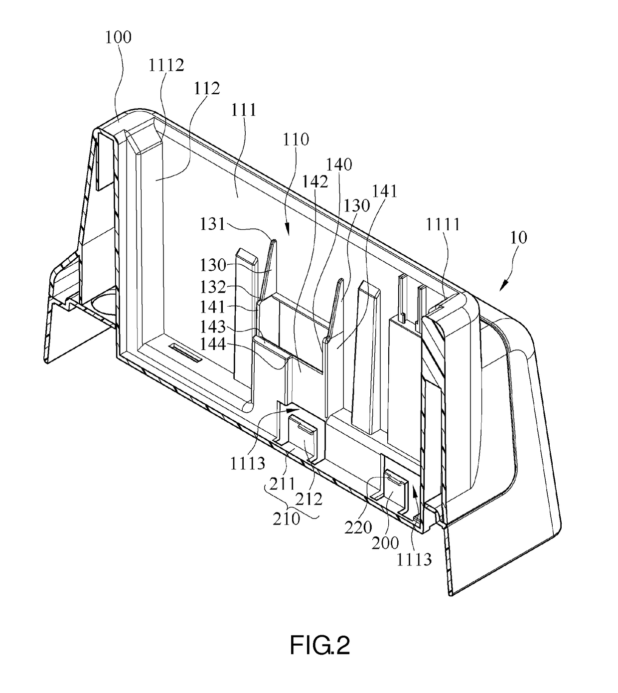
[0025]FIG. 2 a cross-sectional view of the charging base 100 and a hook portion 200 according to the embodiment of the present invention. Referring to FIG. 1 and FIG. 2, in this embodiment, the charging device 10 further comprises the hook portions 200, and the charging bases 100 each have therein two hook portions 200, but the present invention is not limited thereto. In another embodiment, each charging base has one or at least three hook portions. The charging base 100 has a receiving chamber 110 for receiving a battery applicable to the charging device 10. The receiving chamber 110 comprises a first sidewall 111, a second sidewall 112, a third ...


PUM


Abstract

A charging device including a charging base and at least one hook portion is provided. The charging base has a receiving chamber for receiving a battery. The receiving chamber includes a first sidewall. The first sidewall has a first side and a second side opposing the first side. The hook portion is disposed on the first sidewall, positioned proximate to the first side of the first sidewall, and adapted to fix the battery in place. When the battery begins to rotate under an applied force and therefore disconnect from the hook portion, the fulcrum of the rotating battery is positioned proximate to the second side of the first sidewall. The battery can be firmly inserted into the charging device. It is easy to insert and take out the battery.

Description

BACKGROUND OF THE INVENTIONField of the Invention[0001]The present invention relates to charging devices and more particularly to a charging device for charging a battery.Description of the Prior Art[0002]Plenty electrical appliances (especially portable electrical appliances) are powered by built-in batteries. The batteries built in the electrical appliances are of two categories, namely non-separable batteries and separable batteries. Non-separable batteries are built in the electrical appliances and are not removable. To charge non-separable batteries, it is necessary to connect the electrical appliances directly with a utility power supply network, such as an indoor electrical outlet or the interface of another power supply end. However, those electrical appliances whose batteries are running out of power have to be connected to the utility power supply network continually in order to operate, albeit at the expense of portability. Separable batteries are removable from the elect...

Claims


Application Information

Patent Timeline
Patent Type & Authority Patents(United States)
IPC IPC(8): H02J7/00
CPCH02J7/0045H02J7/007H02J7/0013
Inventor HUANG, TZU-CHIU
Owner GETAC TECH CORP
Why Eureka
Try Eureka