
Differential signal mismatch compensation

Active Publication Date: 2018-07-24
WESTERN DIGITAL TECH INC
View PDF16 Cites 3 Cited by
  • Summary
  • Abstract
  • Description
  • Claims
  • Application Information

AI Technical Summary

Benefits of technology

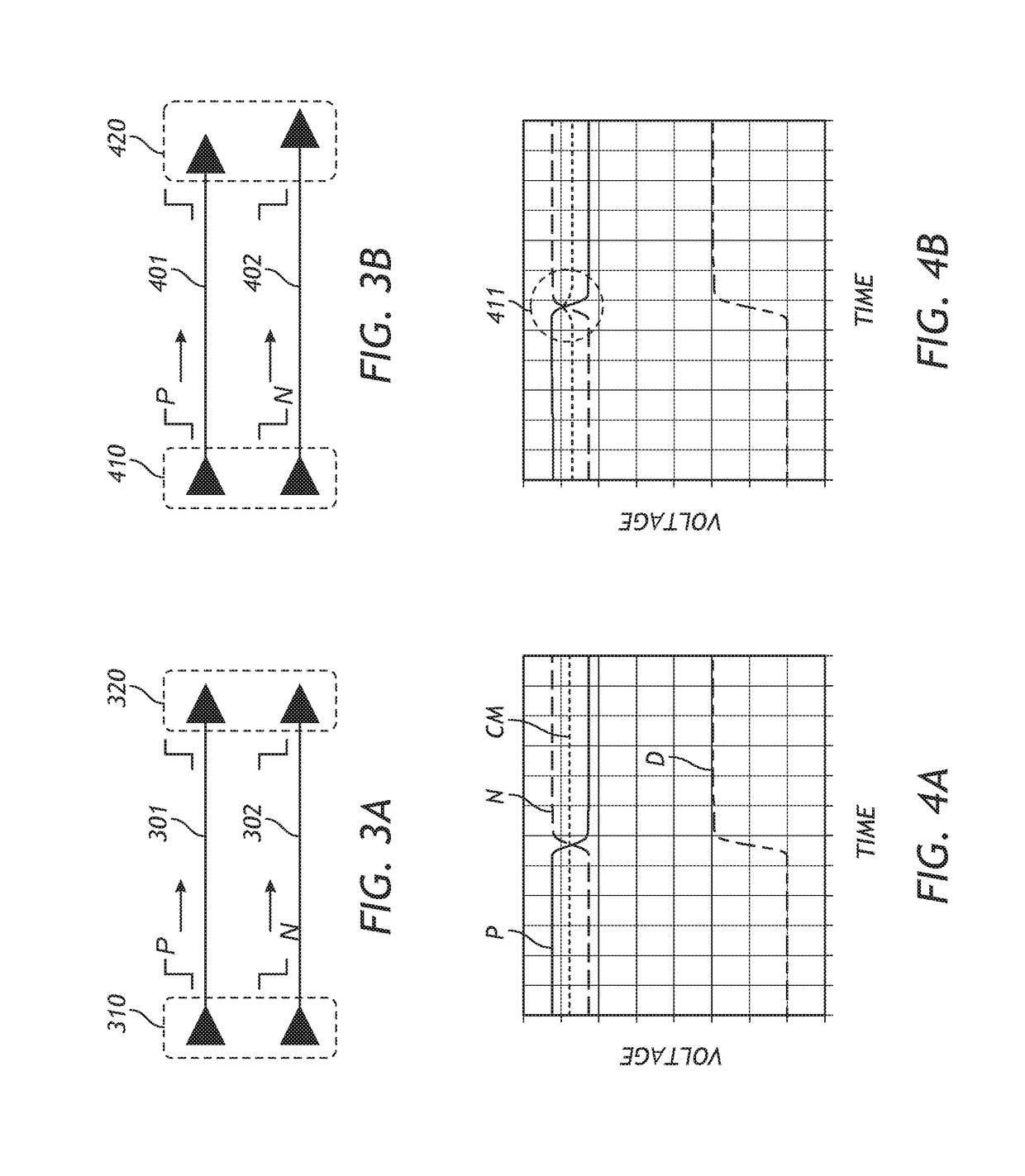
The patent describes a technology that introduces a delay in a signal to reduce phase offset and to compensate for length mismatch between two signal paths. This delay circuitry can be used in a way to create a complementary signal that is opposite in phase to the original signal. Transmitting the two signals over different paths can also be done using a delay circuit, which ensures the signals are synchronized. The delay circuit can be implemented using a phase shifter or a delay-locked loop.

Problems solved by technology

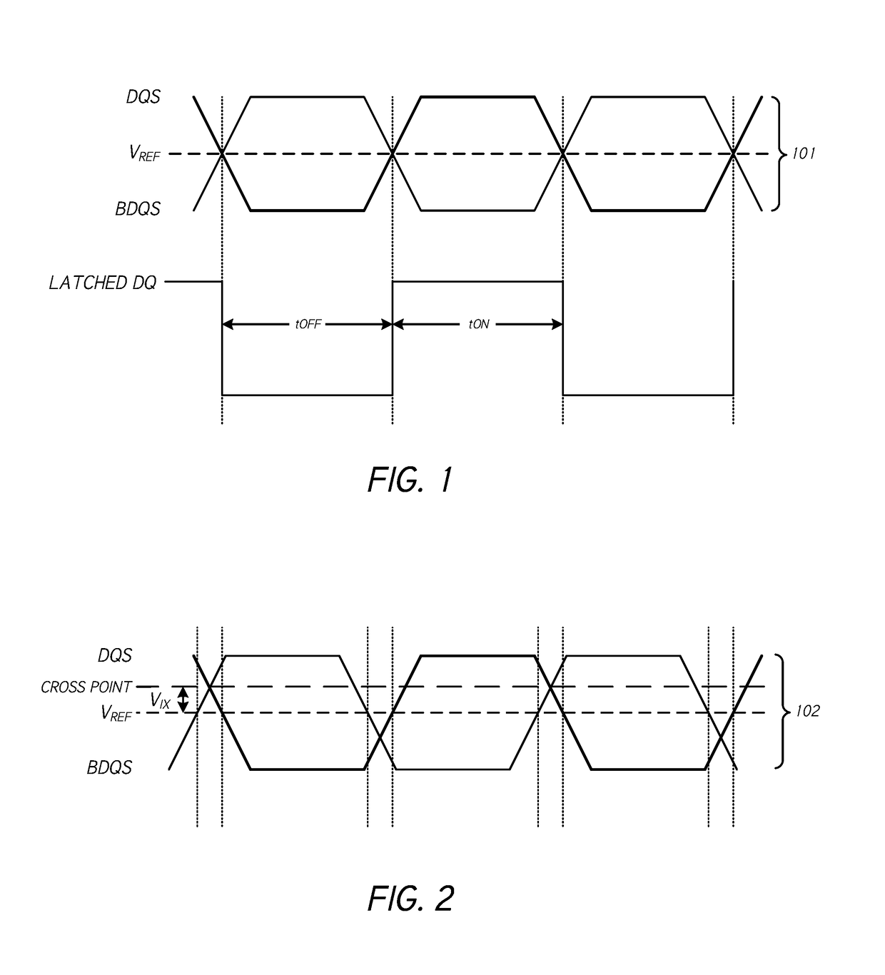
However, where the signal paths used to transmit the differential signals are mismatched, signal integrity can be compromised.

Method used


Image

  • Differential signal mismatch compensation
  • Differential signal mismatch compensation
  • Differential signal mismatch compensation

Examples


Embodiment Construction

[0022]While certain embodiments are described, these embodiments are presented by way of example only, and are not intended to limit the scope of protection. Indeed, the novel methods and systems described herein may be embodied in a variety of other forms. Furthermore, various omissions, substitutions and changes in the form of the methods and systems described herein may be made without departing from the scope of protection.

[0023]The headings provided herein are for convenience only and do not necessarily affect the scope or meaning of the claims. Disclosed herein are example configurations and embodiments relating to backing up data in a computing system.

Overview

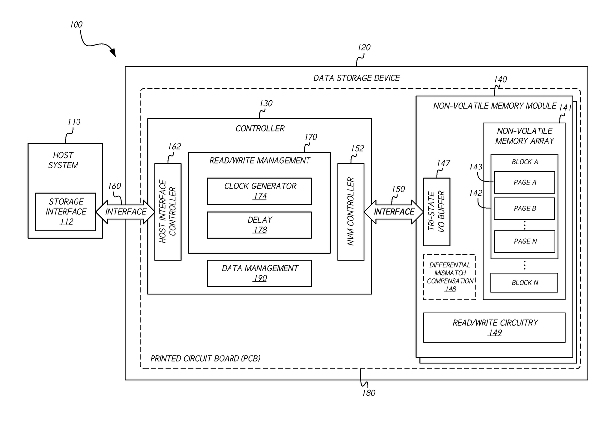
[0024]In computing devices and systems, data may be communicated between components of the system or device through the transmission of signals on one or more data communication / transmission paths. Electronic signal paths may comprise conductive transmission lines or traces, for example. As one example implementation of ...


PUM


Abstract

A computing device includes a complementary signal generator configured to generate first and second complementary signals, delay circuitry configured to introduce a delay in a signal, and control circuitry. The control circuitry is configured to transmit the first and second complementary signals at least in part by determining a length mismatch between first and second signal transmission paths, determining a delay based at least in part on the length mismatch, introducing the delay in the first signal, and providing the delayed first signal and the second signal to the first and second signal paths, respectively.

Description

BACKGROUNDField[0001]This disclosure relates to computing devices and systems. More particularly, the disclosure relates to systems and methods for communicating differential signals in data storage devices and other computing devices and systems.Description of Related Art[0002]In certain computing systems, such as data storage systems, differential signaling can be used to improve signal integrity and / or for other purposes. However, where the signal paths used to transmit the differential signals are mismatched, signal integrity can be compromised.SUMMARY[0003]In some implementations, the present disclosure relates to a data storage device controller, or a controller of another type of computing device, configured to implement differential signal mismatch compensation with respect to communications between the controller and a non-volatile memory module, or other module. For example, some embodiments provide a computing device comprising a complementary signal generator configured ...

Claims


Application Information

Patent Timeline
IPC IPC(8): H04L12/26H04L7/00H04B17/00H04L7/033
CPCH04L7/033H04L43/04H04B17/0085H04L43/0852H04L7/0033H04B17/101H04B17/103H04B17/104H04B17/14H04L25/0272
Inventor SIDDAIAH, VINAY
Owner WESTERN DIGITAL TECH INC
Learn More