
Method and apparatus for rapid and scalable testing of antennas

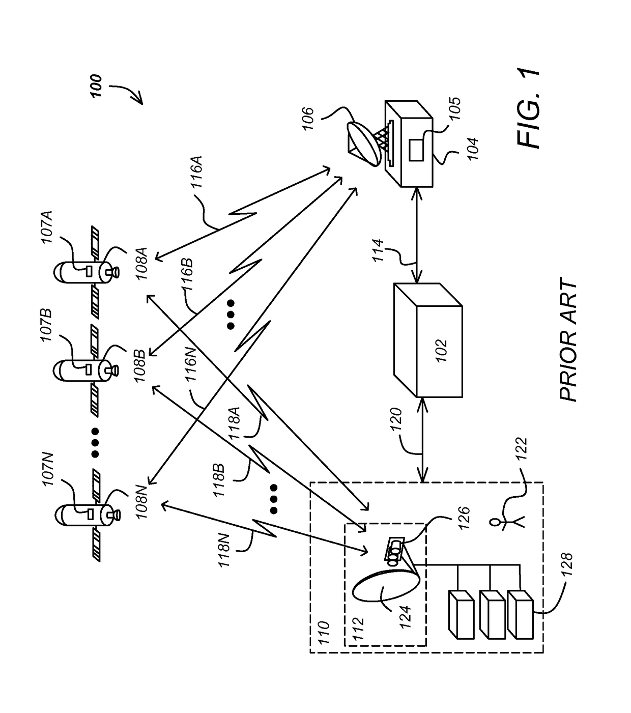
a technology of antennas and antenna radiation diagrams, applied in electrical apparatus, antennas, antenna radiation diagrams, etc., can solve the problems of large and unsightly dish antennas, difficult installation, and required professional installation, and achieve the effect of easy installation, visual unobtrusiveness of small dish antennas

Active Publication Date: 2018-09-25
DIRECTV LLC
View PDF9 Cites 13 Cited by
  • Summary
  • Abstract
  • Description
  • Claims
  • Application Information

AI Technical Summary

Benefits of technology

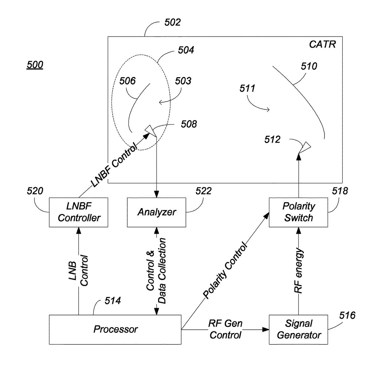
This patent describes a way to test the performance of an antenna system by using a smaller reflector for testing, called a test antenna reflector, instead of the actual operational antenna system reflector. The test reflector is placed in a position relative to the operational antenna system and provides electromagnetic energy to the antenna feed through the reflector. The output of the antenna system is then determined and used to determine the characteristics of the system. The technical effect of this method is that it allows for easier and more efficient testing of antenna systems without having to use the actual operational reflector.

Problems solved by technology

Typically, however, these dish antennas were large and unsightly, and required professional installation.
These smaller dish antennas are visually unobtrusive and much easier to install.
However, such testing is typically prohibitively expensive because accurate testing requires that the testing be performed in large anechoic chambers which are not easily incorporated into an assembly line.

Method used


Image

  • Method and apparatus for rapid and scalable testing of antennas
  • Method and apparatus for rapid and scalable testing of antennas
  • Method and apparatus for rapid and scalable testing of antennas

Examples


Embodiment Construction

[0025]In the following description, reference is made to the accompanying drawings which form a part hereof, and which is shown, by way of illustration, several embodiments of the disclosed system and method. It is understood that other embodiments may be utilized and structural changes may be made without departing from the scope of the disclosure and claims.

Overview

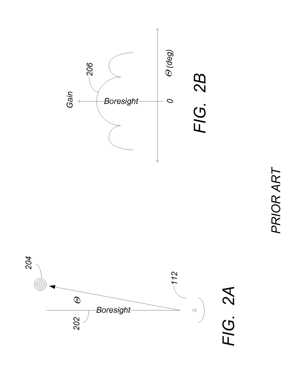
[0026]This disclosure describes production-friendly system and method of measuring performance characteristics of antennas and their components. Such characteristics include the cross-polarization of low noise block converter with feed (LNBF), antenna gain and adjacent satellite rejection.

[0027]Cross polarization of the LNBF is measured by reflecting the signal off of a miniaturized reflector that is a scaled version of the reflector actually used in the final production antenna. Strong correlation between the measured cross-polarization performance using the scaled reflector and using the operational reflector is obser...


PUM


Abstract

A system and method for testing an antenna feed to be incorporated into an operational antenna is disclosed. The system and method uses a scaled reflector with the antenna feed to permit testing that correlates well with a full sized reflector, yet permits testing in a quiet zone of a compact antenna test range. Embodiments are also disclosed for offset feed designs.

Description

BACKGROUND1. Field of the Invention[0001]This disclosure relates to systems and methods for measuring antenna characteristics, and in particular to a system and method for measuring the characteristics of offset feed dish antennas.2. Description of the Related Art[0002]Traditionally, television programming has been delivered to viewers at home by very high frequency (VHF) and ultra high frequency (UHF) transmission from local broadcasting facilities. In the 1980s, dish antennas and receivers became available, allowing home viewers to receive television programming directly from satellite transmissions. Typically, however, these dish antennas were large and unsightly, and required professional installation. In the 1990s, satellite television service evolved to include smaller offset-feed dish antennae and specially designed receivers. These smaller dish antennas are visually unobtrusive and much easier to install.[0003]One means to assure adequate performance of the dish antennas is ...

Claims


Application Information

Patent Timeline
Patent Type & Authority Patents(United States)
IPC IPC(8): G01R29/10H01Q19/12
CPCG01R29/10H01Q19/12
Inventor WU, TERENCECHEN, ERNEST C.
Owner DIRECTV LLC
Learn More