Adaptive application of metal artifact correction algorithms

an image artifact correction and adaptive technology, applied in image enhancement, image analysis, instruments, etc., can solve the problems of image artifacts in ct images, and the best algorithms known so far occasionally create new artifacts, and achieve the effect of removing the corrective weigh

Active Publication Date: 2018-10-02
KONINK PHILIPS ELECTRONICS NV
View PDF8 Cites 1 Cited by
  • Summary
  • Abstract
  • Description
  • Claims
  • Application Information

AI Technical Summary

Benefits of technology

[0031]Dynamically adjusting the neighbourhood size (measured in number of pixels or voxels) allows to keep the run-time of the algorithm at bay as this would increase with neighbourhood size. Choosing the threshold entropy value allows to balancing size for run-time: the entropy cost function may turn out rather flat for a too small a neighbourhood size due to lack of image information or structure in the small neighbourhood. A too large a neighbourhood however is computationally prohibitive and it further impedes a proper correction of artifact present in a small region.

Problems solved by technology

Metal implants or other high density parts often cause image artifacts in CT images.
However, there is the remaining problem that even the best algorithms known so far occasionally create new artifacts.

Method used


Image

  • Adaptive application of metal artifact correction algorithms
  • Adaptive application of metal artifact correction algorithms
  • Adaptive application of metal artifact correction algorithms

Examples


Embodiment Construction

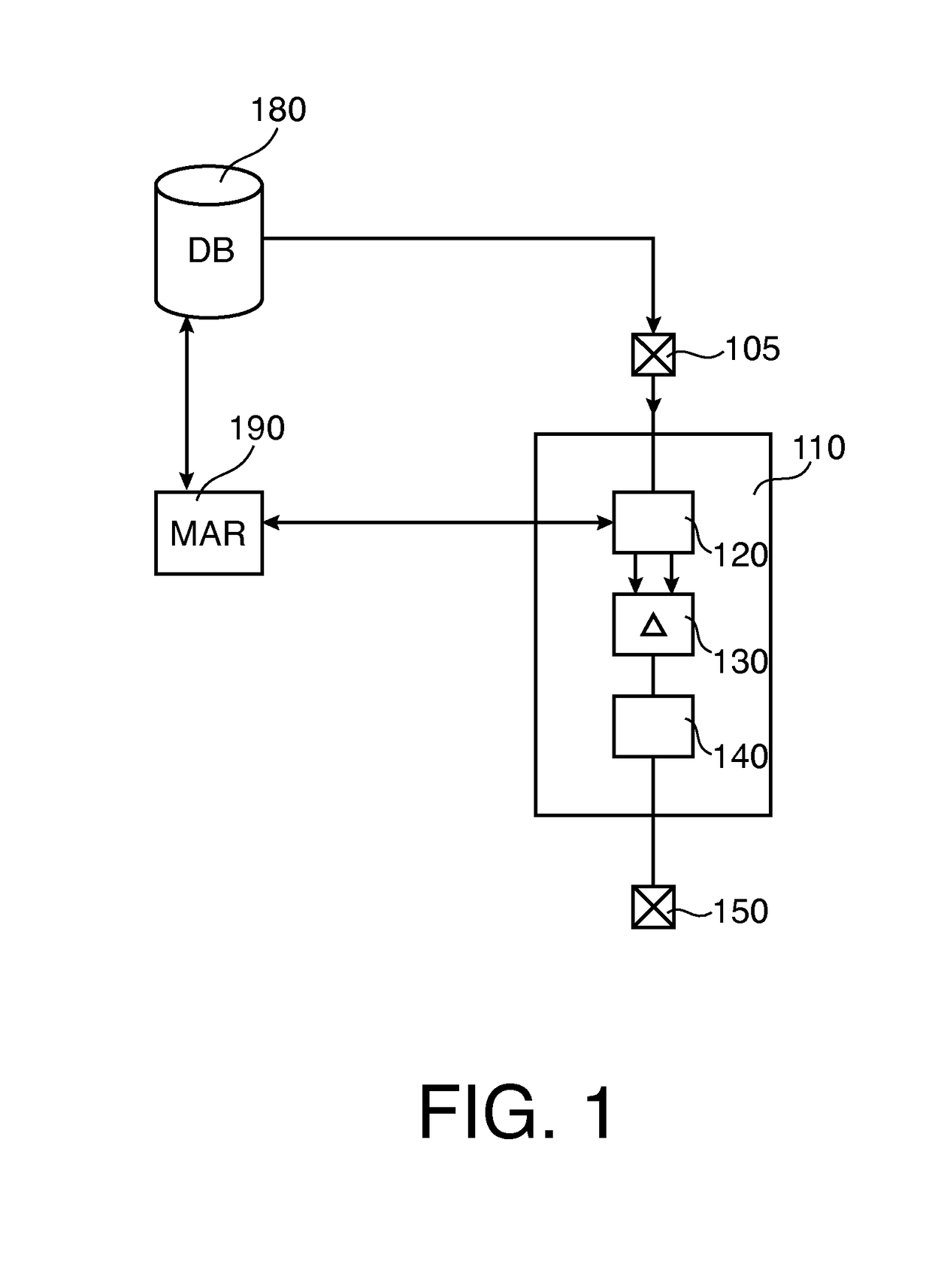
[0043]To the right of FIG. 1 there is shown a block diagram of an apparatus for correcting an image for an artifact.

[0044]The apparatus comprises an input unit or interface means 105, a processing unit 110 and an output unit or interface means 150.

[0045]Input 105 is configured to access a data base system 180 to retrieve therefrom an initial digital image having an image artifact.

[0046]Data base 180 may be arranged as a PACS in a medical facility and is holding medical image data such as 2D computed tomography (CT) projection images or reconstructed 2D or 3D cross sectional images, also commonly referred to as slice images or “slices”. The images are in a suitable digital format such as DICOM format. The apparatus is arranged to connect via interface means 105 and a suitable computer communication network to data base 180.

[0047]To the left of FIG. 1 there is shown an artifact corrector module MAR 190 implementing a known metal artifact reduction (MAR) algorithm. The embodiment of th...


PUM


Abstract

An apparatus for and a method of correcting an image for an image artifact. An initial image is corrected by an image artifact corrector (190). The so corrected sample correction image is compared with the initial image to obtain information on the corrective action. The corrective action is then adaptively reapplied by a controller (140) to obtain an improved corrected image thereby ensuring previously present artifacts are removed and creation of new artifacts are avoided.

Description

CROSS REFERENCE TO RELATED APPLICATIONS[0001]This application is a national filing of PCI application Serial No. PCT / IB2012 / 056041, filed Oct. 31, 2012, published as WO 2013 / 068887 A1 on May 16, 2013, which claims the benefit of U.S. provisional application Ser. No. 61 / 556,859 filed Nov. 8, 2011, which is incorporated herein by reference.FIELD OF THE INVENTION[0002]The invention relates to an apparatus for correcting an image for an image artifact, to a method of correcting an image for an image artifact, to a medical image processing system for correcting an image for an image artifact, to a computer program product, and to a computer readable medium.BACKGROUND OF THE INVENTION[0003]Metal implants or other high density parts often cause image artifacts in CT images. Metal artifact reduction (MAR) algorithms are know which reduce the image artifacts in most cases. An MAR algorithm is known from U.S. Pat. No. 7,991,243.[0004]However, there is the remaining problem that even the best ...

Claims


Application Information

Patent Timeline
Patent Type & Authority Patents(United States)
IPC IPC(8): G06T5/00G06T5/20
CPCG06T5/002G06T5/005G06T5/20G06T2207/30004G06T2207/10116G06T2207/20012G06T2207/20182G06T2207/10081
Inventor KOEHLER, THOMASBRENDEL, BERNHARD JOHANNES
Owner KONINK PHILIPS ELECTRONICS NV
Why Eureka
Try Eureka