Visualizing vascular structures

a technology for visualizing vascular structures and structures, applied in image enhancement, instruments, angiography, etc., can solve problems such as affecting the quality of subtraction images, and achieve the effects of preventing the occurrence of subtraction artifacts, reducing motion artifacts in abdominal dsa, and reducing motion artifacts

Active Publication Date: 2021-06-24
KONINKLJIJKE PHILIPS NV
View PDF0 Cites 0 Cited by
  • Summary
  • Abstract
  • Description
  • Claims
  • Application Information

AI Technical Summary

Benefits of technology

[0015]According to an embodiment, it is proposed to reduce motion artifacts in abdominal DSA through a spatio-temporal approach. This performs a strong reduction of the amplitude of soft tissues in the spatial domain prior temporal subtraction that results in a reduction of motion artifacts after temporal subtraction. The proposed approach performs better than current methods used to compensate for motion artifacts after subtraction. The present approach overcomes the difficulty of motion estimation in transparent layers by a combination of spatial and temporal subtractions. This aims at correcting a combination of various motion sources and types.
[0016]It is proposed to prevent the occurrence of subtraction artifacts rather than correct for artifacts. In particular, two spatial subtractions are performed, one in the mask frames and one in the live frames, prior to a temporal subtraction of mask and live frames. As a result, the amplitude of motion artifacts is reduced.

Problems solved by technology

In case of motion, and in particular breathing or bowel gas motion, the quality of subtracted images may be affected and the resulting artifacts may influence the diagnostic value of the images.

Method used


Image

  • Visualizing vascular structures
  • Visualizing vascular structures
  • Visualizing vascular structures

Examples


Embodiment Construction

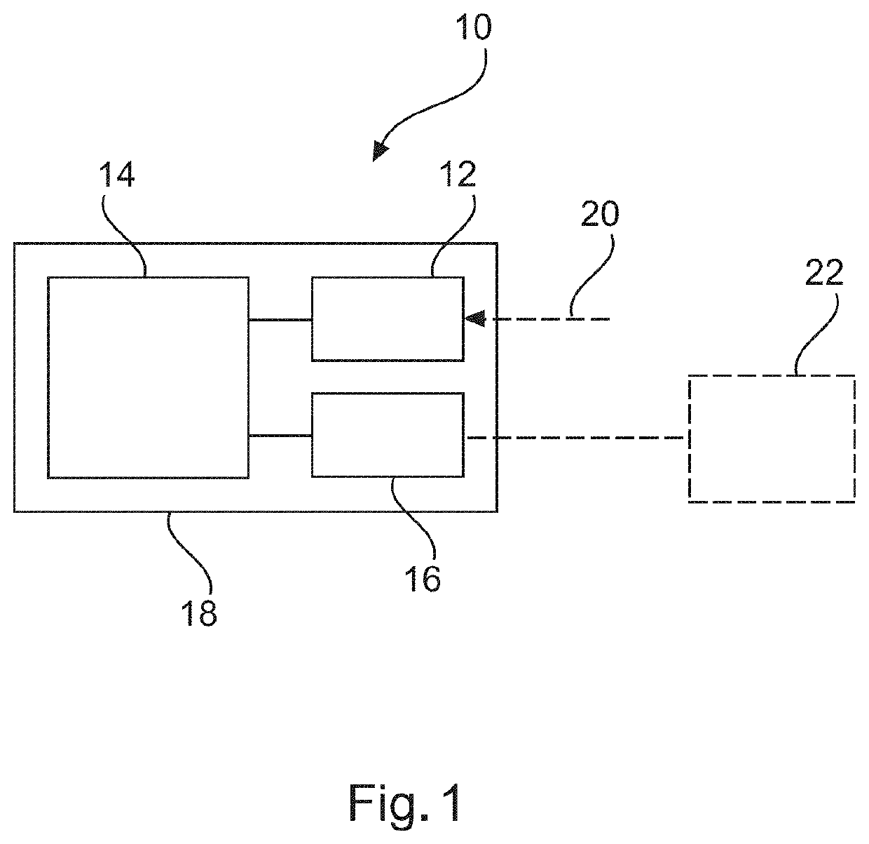
[0026]FIG. 1 shows an example of a device 10 for visualizing vascular structures. The device 10 comprises a data provision processor 12, a data image processor 14, and an output interface 16.

[0027]The data provision processor 12 is configured to provide a first sequence of non-contrast X-ray images of a region of interest of a patient for use as raw X-ray mask images. The data provision processor 12 is also configured to provide a second sequence of contrast X-ray images of the region of interest of a patient for use as raw X-ray live-images.

[0028]The image processor 14 is configured to perform a first spatial subtraction for the first sequence of non-contrast X-ray images resulting in a first sequence of spatial-subtracted mask images. The image processor 14 is also configured to perform a second spatial subtraction for the second sequence of contrast X-ray images resulting in a second sequence of spatial-subtracted X-ray live-images. The image processor 14 is further configured to...


PUM


Abstract

A system, device, and method for visualizing vascular structures is disclosed. According to some implementations, in order to provide further improved digital subtraction angiography, a device for visualizing vascular structures is provided that includes a data provision processor, an image processor, and an output. The data provision processor is configured to provide a first sequence of non-contrast X-ray images of a region of interest of a patient for use as raw X-ray mask images. The data provision processor is also configured to provide a second sequence of contrast X-ray images of the region of interest of a patient for use as raw X-ray live-images. The image processor is configured to perform a first spatial subtraction for the first sequence of non-contrast X-ray images resulting in a first sequence of spatial-subtracted mask images. The image processor is also configured to perform a second spatial subtraction for the second sequence of contrast X-ray images resulting in a second sequence of spatial-subtracted X-ray live-images. The image processor is further configured to perform a temporal subtraction by subtracting the spatial-subtracted mask images from the spatial-subtracted X-ray live-images resulting in a sequence of spatial-temporal subtracted X-ray live-images. The output is configured to output the sequence of spatial-temporal subtracted X-ray live-images.

Description

CROSS-REFERENCE TO RELATED APPLICATIONS[0001]This application is a continuation of U.S. application Ser. No. 16 / 469,396 filed on Jun. 13, 2019, which is a U.S. National Phase application under 35 U.S.C. § 371 of International Application No. PCT / EP2017 / 082895, filed on Dec. 14, 2017, which claims the benefit of European Patent Application No. 16306688.9, filed on Dec. 15, 2016. These applications are hereby incorporated by reference herein in their entirety.FIELD[0002]The present invention relates to visualizing vascular structures, and relates in particular to a device for visualizing vascular structures, to a medical imaging system and to a method for visualizing vascular structures.BACKGROUND[0003]In interventional X-ray imaging, digital subtraction angiography (DSA) may be performed to visualize vascular structures. To emphasize the vascular structures, contrast agent is injected. Images may be obtained by subtracting a non-injected mask frame from injected frames. In case of mo...

Claims


Application Information

Patent Timeline
Patent Type & Authority Applications(United States)
IPC IPC(8): A61B6/00G06T5/00G06T5/50
CPCA61B6/463A61B6/4441A61B6/504G06T2207/20224G06T5/002G06T5/50G06T2207/10116A61B6/5264A61B6/12A61B6/481
Inventor ROUET, LAURENCEFLORENT, RAOUL
Owner KONINKLJIJKE PHILIPS NV
Why Eureka
Try Eureka