Iterative methods for dose reduction and image enhancement in tomography

a tomography and image enhancement technology, applied in image enhancement, instruments, applications, etc., can solve the problems of reducing resolution, missing projection data, and projections that can be acquired in the typical, so as to reduce radiation flux, reduce the number of projections, and reduce the dose

Inactive Publication Date: 2009-09-17
RGT UNIV OF CALIFORNIA
View PDF33 Cites 29 Cited by
  • Summary
  • Abstract
  • Description
  • Claims
  • Application Information

AI Technical Summary

Benefits of technology

[0039]Another aspect of the invention is to provide a method for reducing the dose that is imparted to the patient or the imaging object in tomographic imaging systems.
[0040]An aspect of the invention is to provide a system and method that can provide detailed two and three dimensional images from a reduced number of projections as well as reduced radiation flux over existing methods to reduce the exposure of the subject to radiation.
[0041]Another aspect of the invention is to provide a method for reducing the acquisition time of projection data in tomographic imaging systems. Fast acquisition times are particularly important in imaging an object that moves during the imaging procedures. Such objects may include the organs of a living organism that are in constant motion like the heart and lungs. Motion artifacts in tomographic imaging can be reduced with fast acquisition times.

Problems solved by technology

The number of projections that can be acquired in the typical tomographic imaging system is limited by factors such as patient dose, time, and limitations in the scanner design which results in a portion of the projection data that is missing from a scan.
The missing projection data can result in decreased resolution and produce artifacts that degrade the image quality of the reconstructed image.

Method used


Image

  • Iterative methods for dose reduction and image enhancement in tomography
  • Iterative methods for dose reduction and image enhancement in tomography
  • Iterative methods for dose reduction and image enhancement in tomography

Examples


example 1

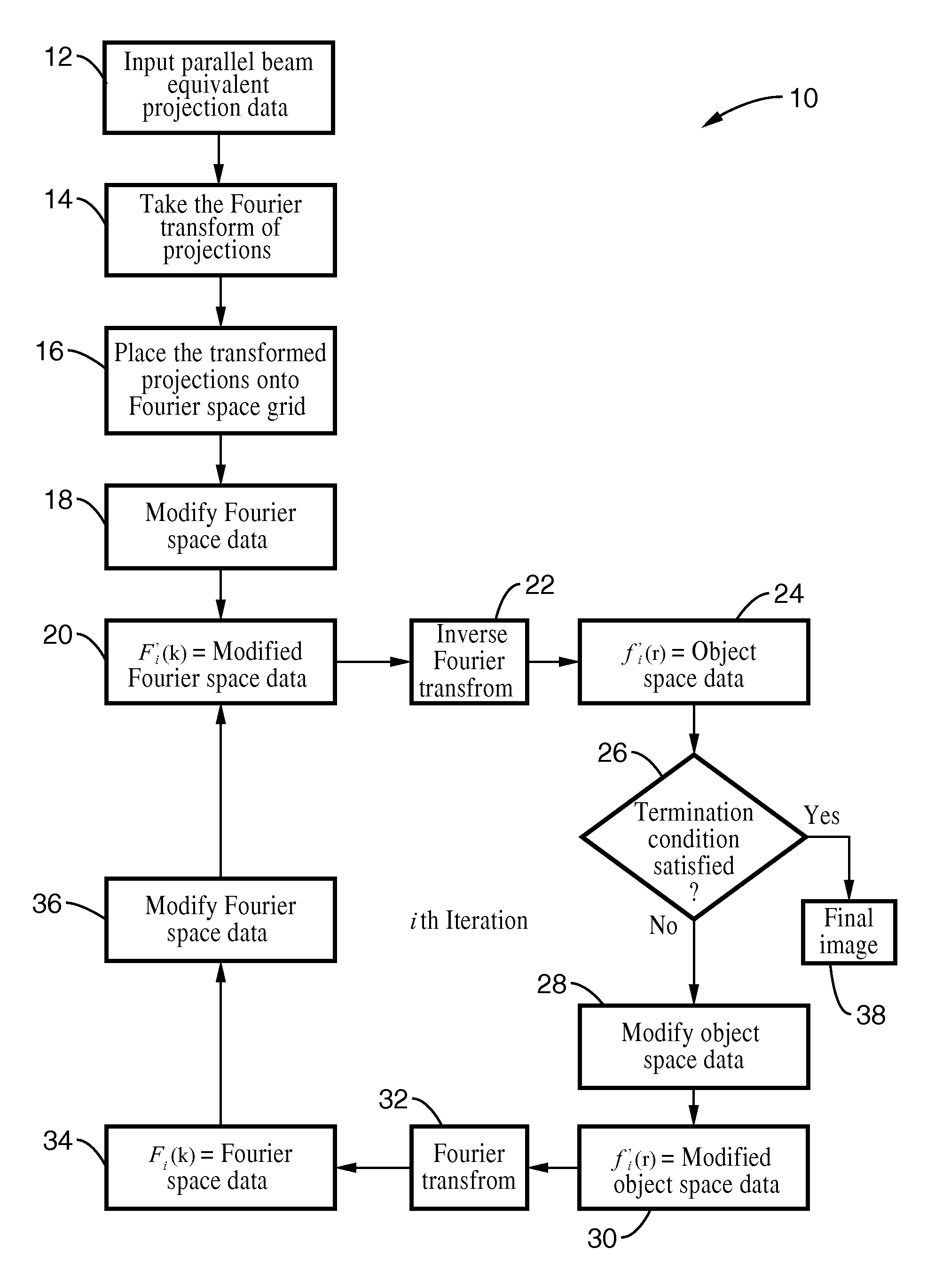
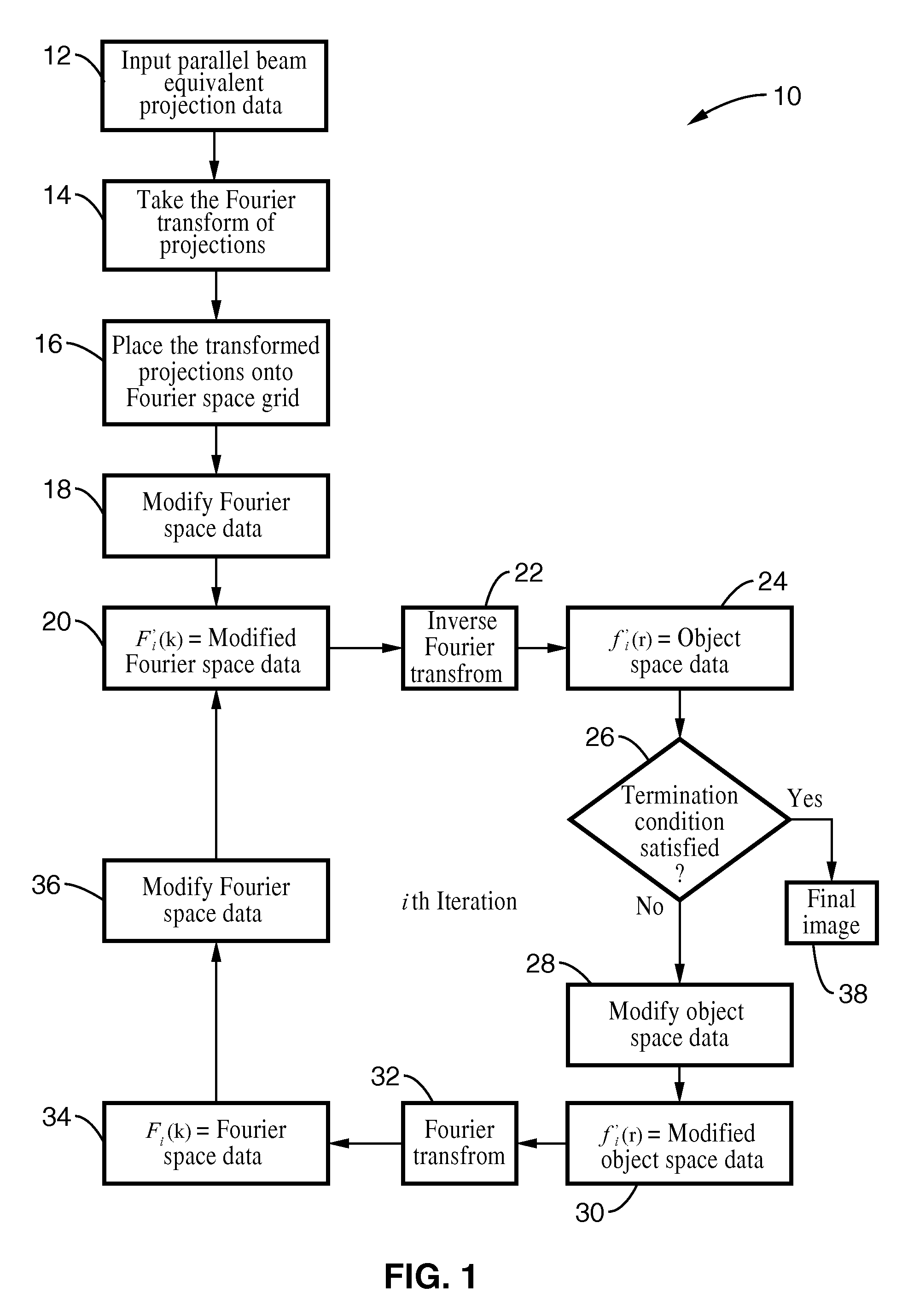
[0116]In order to demonstrate the functionality of the invention, the pseudopolar embodiment of the invention was applied to a 3D image experimental reconstruction of hemocyanin molecules. The hemocyanin molecule consists of a double-layered and hollow barrel complex about 30 nm in diameter and 35 nm in length. A data set was acquired by tilting the specimen from −69.4° to +69.4° with a total of 105 projections. Image reconstruction was carried out using the said method and the conventional method of FBP. The projection data from the imager was padded with zeros, Fourier transformed, placed onto a pseudopolar grid, and translated through the iterative process as described by the solid arrow loop of the diagram of FIG. 3. A positivity constraint was used in object space. In Fourier space, the data was updated and was made to conform to the experimental data. To perform a quantitative comparison, 11 individual hemocyanin molecules of the two reconstructions were chosen. The particles ...

example 2

[0117]To demonstrate the adaptability of the methods of the invention, images of HIV-1 virus-like particles (VLPs) were reconstructed. The subject particles were plunge-frozen onto EM grids and imaged in a 300 kV FEG TEM. The tilt angles ranged from −70° to +70° with a fixed angular increment of 1°. The 3D structure of a HIV-1 VLP was reconstructed by using conventional methods for purposes of comparison with images produced by the present invention. Referring now to FIG. 5A through FIG. 5D, image reconstruction of the HIV-1 like particle from cryo-EM data is shown. FIG. 6 (A) and FIG. 6(B) show sectioned images in the XY and YZ plane with 15-slice averaging and no denoising. The inset shows some of the gold fiducial markers reconstructed by conventional methods.

[0118]The same data set was reconstructed by the pseudopolar embodiment of the present invention. Since the tilt series has a fixed angular increment, it was possible to calculate each equally sloped tilt from the neighborin...


PUM


Abstract

A system and method for creating a three dimensional cross sectional image of an object by the reconstruction of its projections that have been iteratively refined through modification in object space and Fourier space is disclosed. The invention provides systems and methods for use with any tomographic imaging system that reconstructs an object from its projections. In one embodiment, the invention presents a method to eliminate interpolations present in conventional tomography. The method has been experimentally shown to provide higher resolution and improved image quality parameters over existing approaches. A primary benefit of the method is radiation dose reduction since the invention can produce an image of a desired quality with a fewer number projections than seen with conventional methods.

Description

CROSS-REFERENCE TO RELATED APPLICATIONS[0001]This application claims priority from, and is a 35 U.S.C. § 111 (a) continuation of, co-pending PCT international application serial number PCT / US2007 / 075220, filed on Aug. 3, 2007, incorporated herein by reference in its entirety, which claims priority to U.S. application Ser. No. 60 / 835,552, filed on Aug. 3, 2006, incorporated herein by reference in its entirety.STATEMENT REGARDING FEDERALLY SPONSORED RESEARCH OR DEVELOPMENT[0002]This invention was made with Government support under Grant Number DE-FG02-06ER46276 awarded by the Department of Energy. The Government has certain rights in this invention.INCORPORATION-BY-REFERENCE OF MATERIAL SUBMITTED ON A COMPACT DISC[0003]Not ApplicableNOTICE OF MATERIAL SUBJECT TO COPYRIGHT PROTECTION[0004]A portion of the material in this patent document is subject to copyright protection under the copyright laws of the United States and of other countries. The owner of the copyright rights has no obje...

Claims


Application Information

Patent Timeline
Patent Type & Authority Applications(United States)
IPC IPC(8): G06K9/36G06K9/00
CPCG06T11/006A61B6/508G06T2211/424G01T1/161A61B6/00G01T1/00
Inventor MIAO, JIANWEIFAHIMIAN, BENJAMIN POOYA
Owner RGT UNIV OF CALIFORNIA
Why Eureka
Try Eureka