Methods for reducing motion artifacts in shear wave images

a technology of motion artifacts and shear wave, applied in the field of diagnostic imaging, can solve the problems of probe and patient motion artifacts, shear wave displacement images, and the like, and achieve the effect of reducing motion artifacts

Active Publication Date: 2013-01-31
GENERAL ELECTRIC CO
View PDF9 Cites 35 Cited by
  • Summary
  • Abstract
  • Description
  • Claims
  • Application Information

AI Technical Summary

Benefits of technology

[0010]Certain aspects of the present technique are drawn to exemplary methods for reducing motion artifacts in shear wave measurements. The methods include delivering one or more reference pulses to a common motion tracking location and to a plurality of target locations in a region of interest of a subject to detect initial positions of the common motion tracking location and the plurality of target locations. Further, a shear wave is generated in the region of interest. Additionally, one or more tracking pulses are delivered to the common motion tracking location and to the plurality of target locations for determining corresponding displacements. The methods compute an average value of displacement of the common motion tracking location. Further, the methods estimate a motion corrected displacement for a target location in the plurality of target locations based on a displacement of the target location at a particular time, the corresponding displacement of the common tracking location measured proximate in time to the measurement of the displacement of the target location and the average value of displacement of the common motion tracking location.
[0011]Another aspect of the present technique includes further methods for reducing motion artifacts in shear wave measurements. To that end, the methods deliver at least two groups of shear wave scan sequences. Each of these groups comprises delivering one or more reference pulses to a first set of target locations in a region of interest of a subject to detect corresponding initial positions, where at least one of the first set of target locations is common to a second set of target locations. Further, a shear wave is generated in the region of interest. One or more tracking pulses are then delivered to the first set of target locations for determining corresponding displacements. Further, displacements for the first set of target locations are computed based on measurements captured using the one or more reference pulses and the one or more tracking pulses delivered to the corresponding target locations in the first set of target locations. Particularly, for each group of shear wave sequences, the determined displacements for the first set of target locations and the second set of target locations is interpolated to a common time. Further, a difference between the interpolated displacement of a target location in the first set of target locations and the interpolated displacement of another target location in the first set of target locations is computed. Additionally, the methods include estimating a seed value using the measured and interpolated displacements from the target location in the first set of target locations. Motion corrected displacements for other target locations in the first set of target locations are estimated based on the estimated seed value and the computed difference between interpolated displacement of the target location and the interpolated displacement of another target location in the first set of target locations. Additionally, motion corrected displacements for the second set of target locations are estimated using the computed difference and the motion corrected displacements estimated for target locations in the first set of target locations that are common to the second set of target locations.
[0013]One technical effect of the methods and systems of the present disclosure is for reducing appearance of motion artifacts during shear wave imaging. In particular, a technical effect prevents or at least substantially reduces the motion artifacts such as image blur, decorrelation, and / or axial stripes when imaging biological tissues using multiline acquisitions.

Problems solved by technology

Conventional shear velocity imaging techniques, however, suffer from probe and patient motion artifacts such as image blur, decorrelation, and groupings or stripes along the axial direction.
In particular, movement of the ultrasound probe relative to the patient or internal motion such as respiration, cardiac motion, tremors and / or vibrations during the course of the multiple acquisitions can also corrupt the measured displacements.
Similarly, other movements such as respiration may cause displacements of varying orders resulting in artifacts in the shear wave displacement images.
Attempts to prevent appearance of motion artifacts due to background and / or patient motion using mitigating approaches such as specifically designed motion filters are often complex and require additional processing time and expense.

Method used


Image

  • Methods for reducing motion artifacts in shear wave images
  • Methods for reducing motion artifacts in shear wave images
  • Methods for reducing motion artifacts in shear wave images

Examples


Embodiment Construction

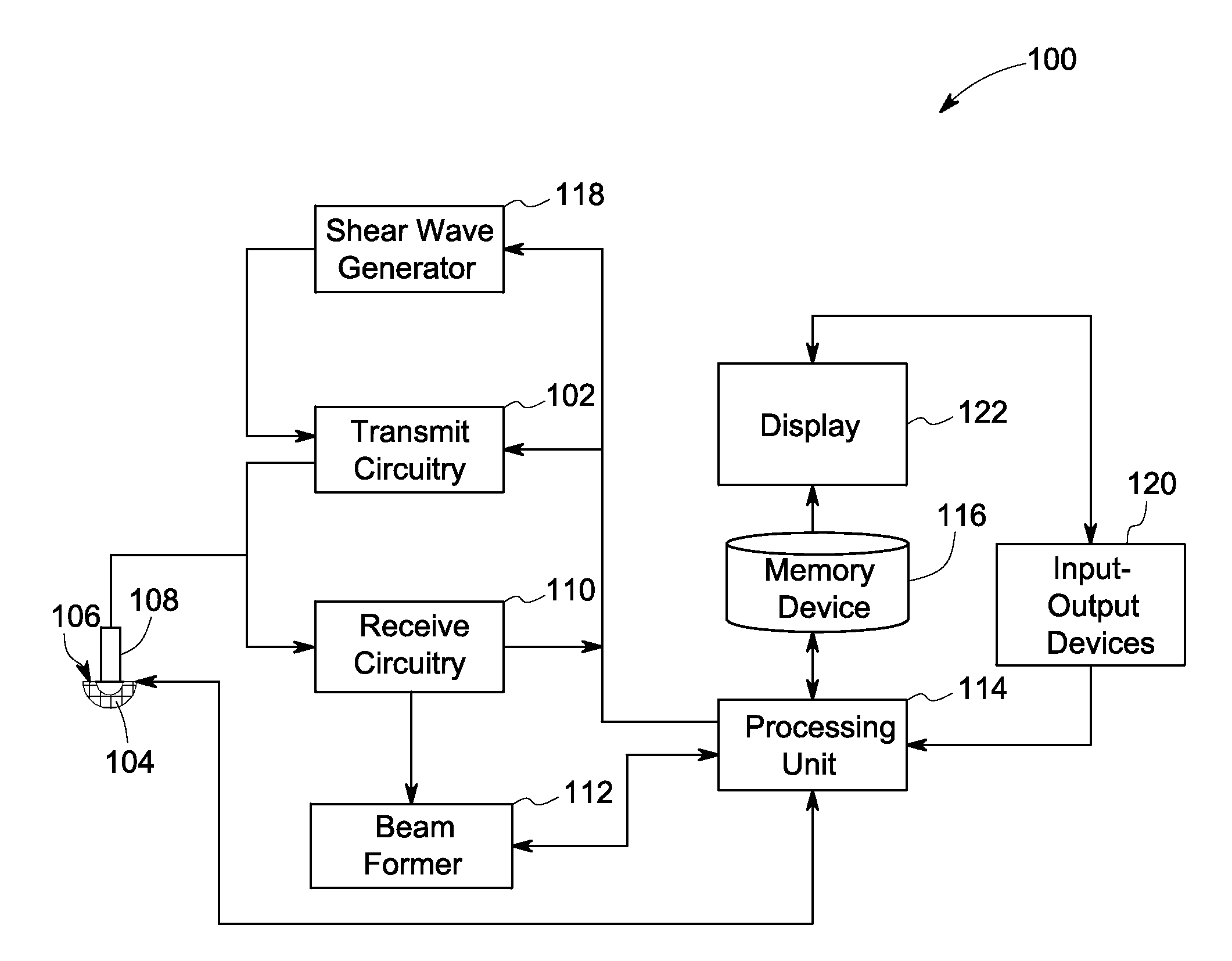
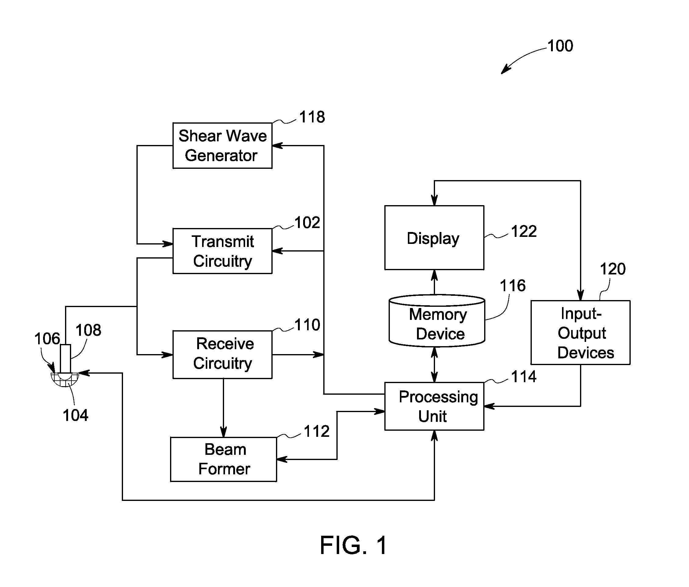
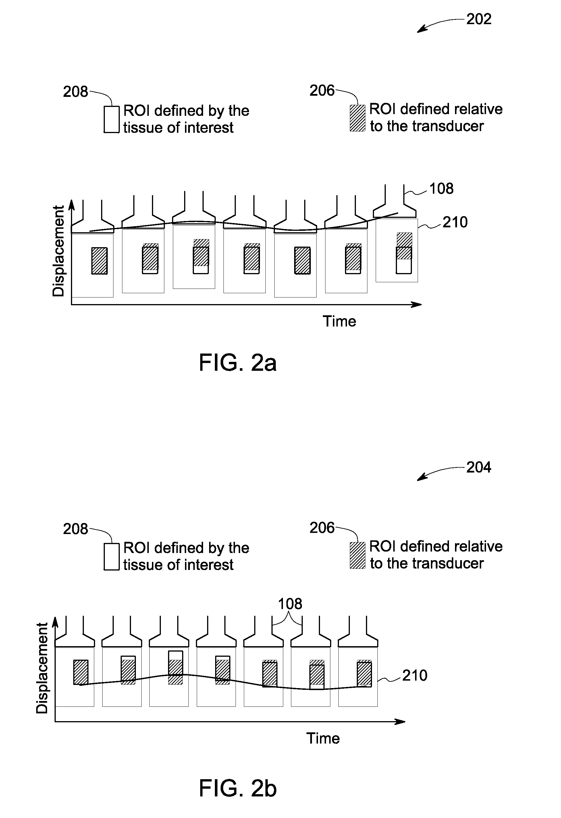
[0025]The following description presents systems and methods for reducing appearance of motion artifacts in shear wave displacement images. Particularly, certain embodiments illustrated herein describe the systems and the methods that efficiently mitigate the errors in the measured displacement values of one or more target locations in the ROI of a subject by evaluating the measured values with reference to the displacements measured at one or more tracking locations. The systems and methods use the evaluation for substantially improving the estimation of motion-corrected displacement values of the target locations, which in turn, reduces motion artifacts in the corresponding reconstructed images.

[0026]Although the following description includes embodiments relating to ultrasound imaging, the various embodiments may also be implemented in connection with other types of medical imaging systems, such as magnetic resonance imaging (MRI) systems, computed-tomography (CT) systems, and sy...


PUM


Abstract

Methods and non-transitory computer readable media that store executable instructions to perform a method for reducing motion artifacts in shear wave measurements are presented. Accordingly, reference pulses are delivered to a common motion tracking location (CMTL) and a plurality of target locations in a region of interest (ROI) to detect corresponding initial positions. Further, a shear wave is generated and tracked in the ROI using tracking pulses delivered to the CMTL and the plurality of target locations for determining corresponding displacements. Additionally, an average displacement of the CMTL is computed. Further, a motion corrected displacement for a target location in the plurality of target locations is estimated based on a displacement of the target location at a particular time, a corresponding displacement of the CMTL measured proximate in time to the measurement of the displacement of the target location and the average displacement of the CMTL.

Description

STATEMENT OF GOVERNMENT INTEREST[0001]This invention was made with government support under NIH-UR-414115-G awarded by National Institutes of Health. The government has certain rights in the invention.BACKGROUND[0002]Embodiments of the disclosure relate to diagnostic imaging, and more particularly to methods for reducing motion artifacts in shear wave measurements.[0003]Medical diagnostic ultrasound is an imaging modality that employs ultrasound waves to probe the acoustic properties of biological tissues and produce corresponding images. Particularly, diagnostic ultrasound systems are used to visualize muscles, tendons and other internal organs to assess their size, structure and any pathological lesions using near real-time tomographic images. Further, diagnostic ultrasound also finds use in therapeutics where an ultrasound probe is used to guide interventional procedures such as biopsies.[0004]To that end, conventional ultrasound devices include a plurality of transducer elements...

Claims


Application Information

Patent Timeline
Patent Type & Authority Applications(United States)
IPC IPC(8): G06K9/40
CPCA61B8/485A61B8/5276A61B8/469G01S7/52042G01S7/52022
Inventor HAZARD, CHRISTOPHER ROBERT
Owner GENERAL ELECTRIC CO
Why Eureka
Try Eureka