Radio system having a sliding mount for a portable radio and related methods

Active Publication Date: 2018-11-06
HARRIS GLOBAL COMMUNICATIONS INC
View PDF12 Cites 2 Cited by
  • Summary
  • Abstract
  • Description
  • Claims
  • Application Information

AI Technical Summary

Benefits of technology

The patent describes a radio system that includes a portable radio and a mounting rail with indentations. The system has a sliding mount that is attached to the portable radio and can slide along the mounting rail. A spring plunger is provided in the sliding mount that engages with the indentations in the mounting rail. The sliding mount is designed to securely hold the portable radio and minimize movement during use. The system also includes a locking device with a lock body, a manual actuating member, and a locking pin that can be locked and unlocked to secure the portable radio to the mounting rail. The technical effect of this invention is to provide a secure and stable mounting mechanism for portable radios that reduces movement and interference during use.

Problems solved by technology

Portable radios are often used in harsh environments, and in some settings, users mount their radios on vehicles or other locations with radio mounting systems that are cumbersome, prone to vibration, and make adjustment and removal of the portable radios difficult.
Although some conventional radio mounting systems for vehicles or other locations may protect the radio from harsh environments and lessen vibration once attached, however, the portable radio may be difficult to move into a desired position for flexibility and allow ready removal.
Some portable radio mounting systems are time-consuming and cumbersome to install and require specialized tools or thumbscrews to mount a portable radio onto a vehicle, and in some cases, even on a protective vest worn by the user.
These types of radio mounting systems pose technical drawbacks because they do not allow a portable radio to be easily mounted and removed quickly such as on a vehicle subject to vibration or at similar locations where the portable radio may have to be positioned for ready access while also permitting easy removal.

Method used


Image

  • Radio system having a sliding mount for a portable radio and related methods
  • Radio system having a sliding mount for a portable radio and related methods
  • Radio system having a sliding mount for a portable radio and related methods

Examples


Embodiment Construction

[0018]The present description is made with reference to the accompanying drawings, in which exemplary embodiments are shown. However, many different embodiments may be used, and thus, the description should not be construed as limited to the particular embodiments set forth herein. Rather, these embodiments are provided so that this disclosure will be thorough and complete. Like numbers refer to like elements throughout, and prime notation is used to indicate similar elements in different embodiments.

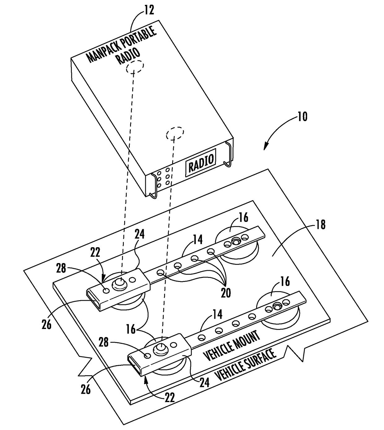
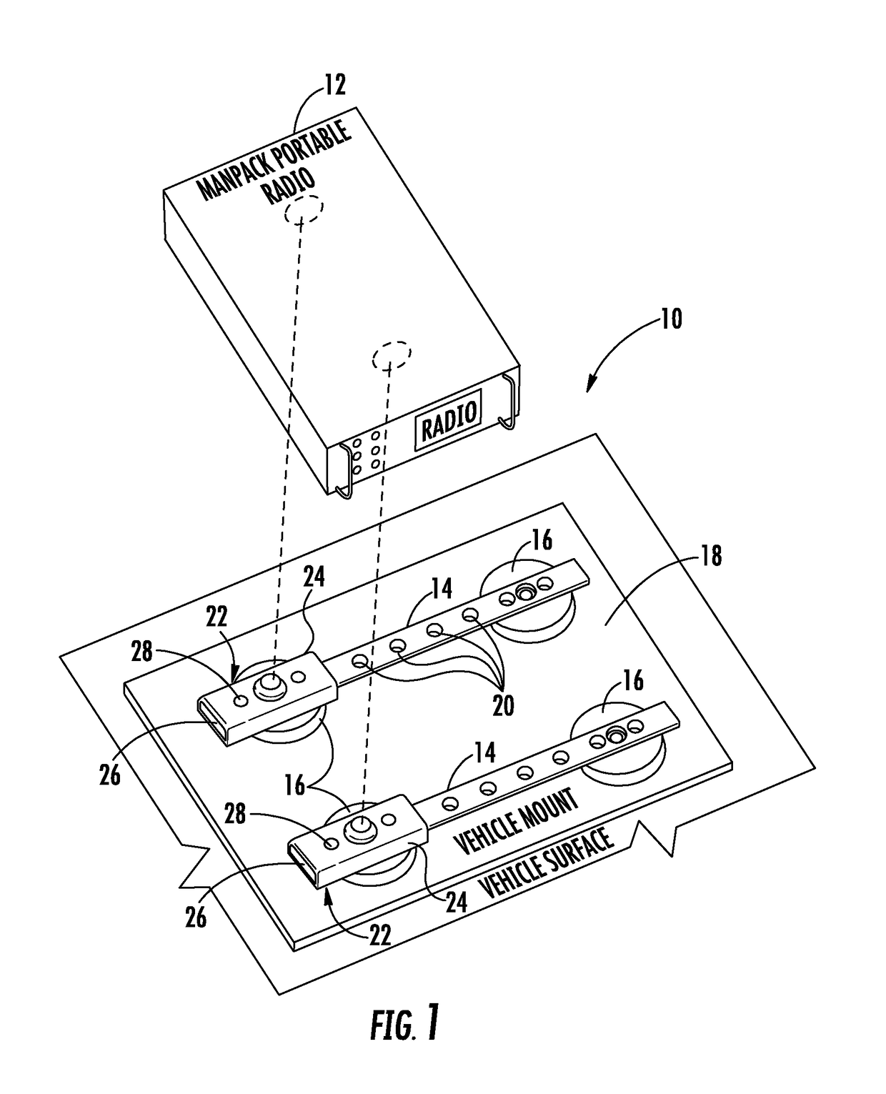
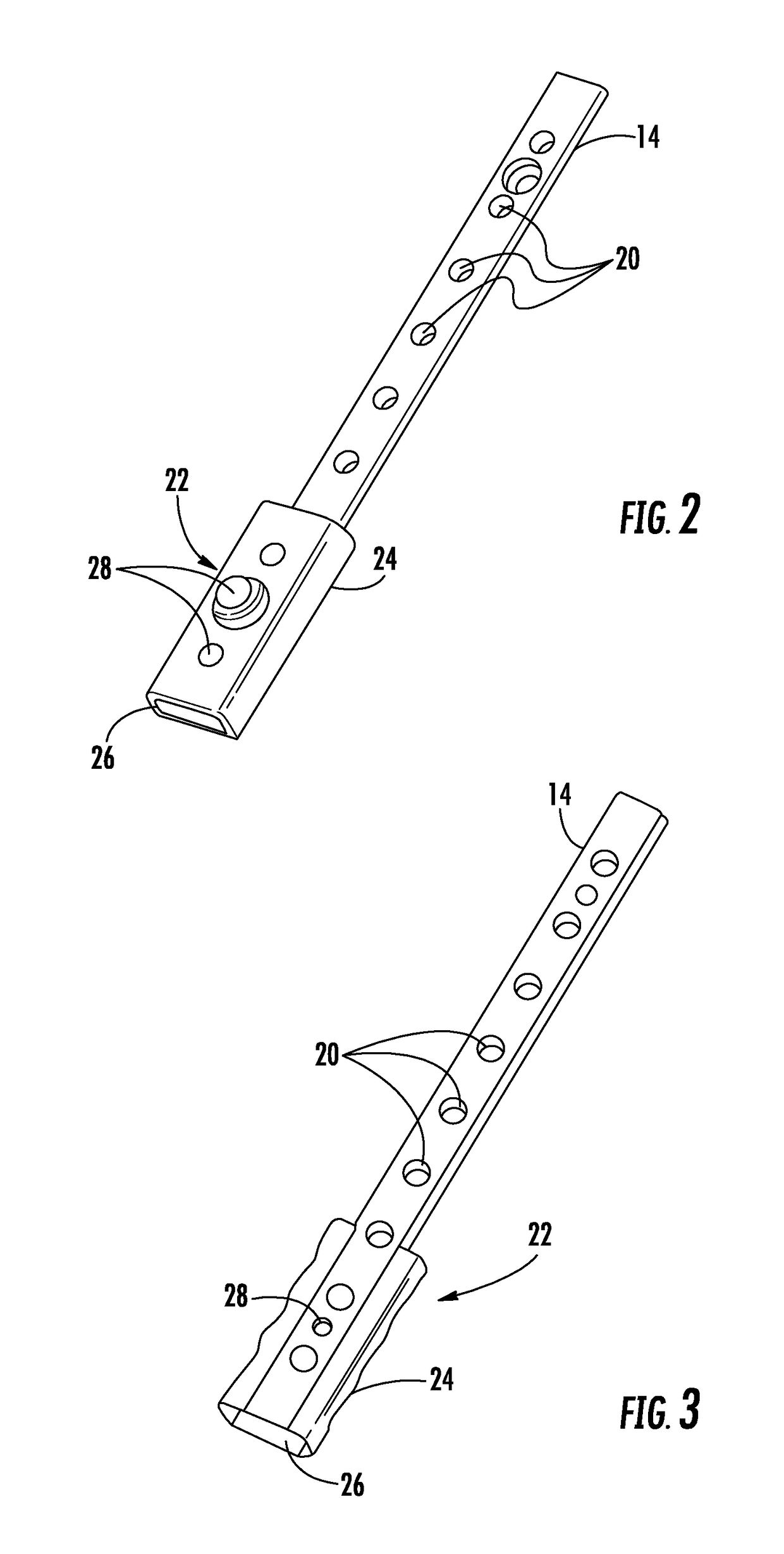
[0019]The radio system permits a portable radio such as a handheld portable radio or a manpack portable radio, for example, such as manufactured by Harris Corporation of Melbourne, Fla., to be coupled to a mount body as part of a sliding mount that receives a corresponding elongate mounting rail. No tools are required to mount or position the portable radio on the elongate mounting rail because it slides and locks in place via an appropriate locking device. The sliding mount may also be...


PUM


Abstract

A radio system includes a portable radio and at least one elongate mounting rail having spaced apart indentations therein. At least one sliding mount includes a mount body having a passageway therethrough and slidably receiving a corresponding elongate mounting rail. The mount body is coupled to the portable radio. At least one spring plunger is carried by the mount body and configured to engage at least one adjacent indentation in the elongate mounting rail.

Description

FIELD OF THE INVENTION[0001]The present invention relates to the field of radio systems, and more particularly, to a radio system having a portable radio received on a mounting rail and related methods.BACKGROUND OF THE INVENTION[0002]Portable radios are often used in harsh environments, and in some settings, users mount their radios on vehicles or other locations with radio mounting systems that are cumbersome, prone to vibration, and make adjustment and removal of the portable radios difficult. These portable radios may be larger radios, such as a manpack portable radio, or the smaller handheld portable radios. Although some conventional radio mounting systems for vehicles or other locations may protect the radio from harsh environments and lessen vibration once attached, however, the portable radio may be difficult to move into a desired position for flexibility and allow ready removal. Some portable radio mounting systems are time-consuming and cumbersome to install and require ...

Claims


Application Information

Patent Timeline
IPC IPC(8): H05K7/00F41C23/16F41G11/00F41A23/08H05K5/00F41G1/387
CPCF41G1/387F41C23/16F41G11/003F41A23/08F41C27/00H04B1/3877B60R11/0205
Inventor FURNESS, RICHARD H.JANUARY, MICHAEL W.FITZSIMMONS, CORY N.
Owner HARRIS GLOBAL COMMUNICATIONS INC
Why Eureka
Try Eureka