Energy storage device stack balancing using switched inductor background

a technology of energy storage devices and background, which is applied in the direction of electrochemical generators, secondary cells servicing/maintenance, transportation and packaging, etc., can solve the problems of dissipating energy within the resistor, moving charge from one cell to another cell several cells away, and not meeting the goals of existing approaches

Active Publication Date: 2019-01-08
ANALOG DEVICES INT UNLTD
View PDF9 Cites 1 Cited by
  • Summary
  • Abstract
  • Description
  • Claims
  • Application Information

AI Technical Summary

Problems solved by technology

Existing approaches may not meet these goals, but may instead require transformers in a fly-back configuration to move energy from a single battery or capacitor back into the stack and vice-versa.
However, moving charge from one cell to another cell several cells away may incur a large efficiency penalty due to the several power conversion steps that may be needed.
However, this approach may dissipate energy within the resistor and may not be able to increase the energy stored in a cell.
However, it can be difficult to move much energy in this way due to the higher output impedance of charge pumps.
This approach can also be very complicated to control and build.

Method used


Image

  • Energy storage device stack balancing using switched inductor background
  • Energy storage device stack balancing using switched inductor background
  • Energy storage device stack balancing using switched inductor background

Examples


Embodiment Construction

[0020]Illustrative embodiments are now described. Other embodiments may be used in addition or instead. Details that may be apparent or unnecessary may be omitted to save space or for a more effective presentation. Some embodiments may be practiced with additional components or steps and / or without all of the components or steps that are described.

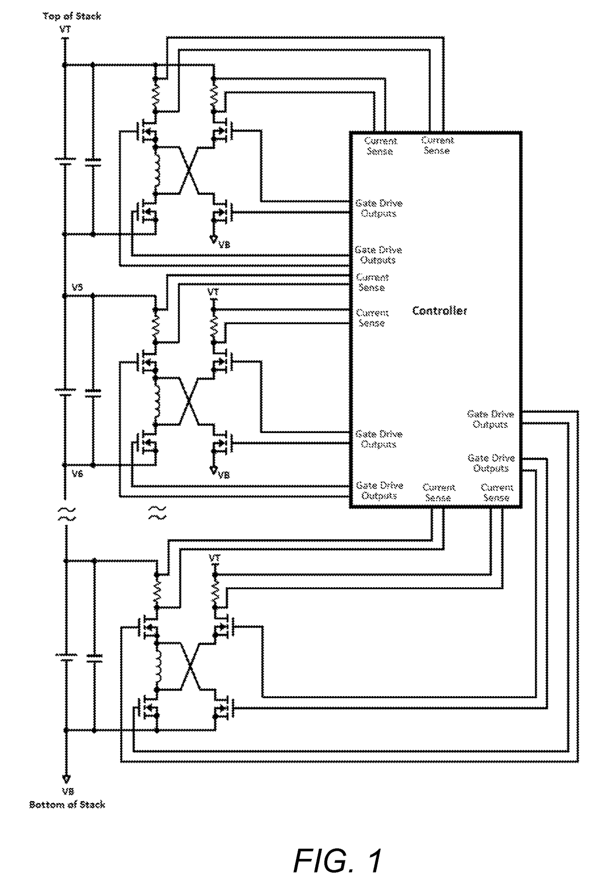
[0021]A DC / DC switching regulator topology may be used to balance a serially connected stack of energy storage elements, such as batteries or capacitors. A single inductor and four switches may be used for each cell in the stack. Alternatively, a more complex switching arrangement may be used with only a single inductor in the entire circuit.

[0022]FIG. 1 illustrates an example of an energy storage stack balancing circuit. This circuit can move energy from the entire battery stack to one cell in the stack and vice-versa. It may not need a transformer to work, which may decrease costs. The stack may be a set of energy storage elements connec...


PUM

PropertyMeasurementUnit
output voltageaaaaaaaaaa

Abstract

An energy storage stack balancing circuit may balance a set of serially connected energy storage devices. An electronic switching system may control the delivery of energy into and out of the inductor. A controller may control the electronic switching system so as to cause energy to be transferred: from one of the energy storage devices into the inductor and then out of the inductor and into a different one, a subset, or all of the energy storage devices; or from a subset of the energy storage devices into the inductor and then out of the inductor and into one, a different subset, or all of the energy storage devices; or from all of the energy storage devices into the inductor and then out of the inductor and into one or a subset the energy storage devices.

Description

TECHNICAL FIELD[0001]This disclosure relates to balancing stored energy in a battery or capacitor stack or other type of energy storage device stack.DESCRIPTION OF RELATED ART[0002]A stack of batteries or capacitors may be connected in series to form a power supply. The stack may have a top voltage VT and a bottom voltage VB. In between VT and VB, there may be a series of voltages drops from top to bottom of V1, V2, . . . VN. These in between voltage points may correspond to terminals joining the consecutive batteries or capacitors making up the stack.[0003]It may be desirable to balance the energy in the stack so that each cell has the same amount of stored energy. To facilitate this, energy may be moved from one cell, such as the cell between V5-V6, and distributed across the entire stack from VT-VB. The opposite operation may also be useful, that is taking energy from the entire stack VT-VB and placing it into the cell between V5-V6.[0004]Similarly, the balancing of energy may be...

Claims


Application Information

Patent Timeline
Patent Type & Authority Patents(United States)
IPC IPC(8): H01M10/44H01M10/46H02J7/00H02J7/34
CPCH02J7/0016H02J7/345H01M10/4207H01M10/425H01M2010/4271H02M3/10H02M3/155Y02E60/10
Inventor WU, ALBERT M.
Owner ANALOG DEVICES INT UNLTD
Why Eureka
Try Eureka