Imaging lens and imaging apparatus

a technology of imaging apparatus and lens, applied in the field of imaging lens, can solve the problem of insufficient correction of distortion, and achieve the effect of satisfactorily correcting distortion, ensuring image quality, and appropriateness

Active Publication Date: 2019-02-19
FUJIFILM CORP
View PDF3 Cites 0 Cited by
  • Summary
  • Abstract
  • Description
  • Claims
  • Application Information

AI Technical Summary

Benefits of technology

[0037]Further, the imaging apparatus of the present invention comprises the imaging lens of the present invention. Thus, it is possible to appropriately capture a high quality image with a wide angle.

Problems solved by technology

However, in the lens system disclosed in JP2012-108302A, correction of distortion is not sufficient.

Method used


Image

  • Imaging lens and imaging apparatus
  • Imaging lens and imaging apparatus
  • Imaging lens and imaging apparatus

Examples


Embodiment Construction

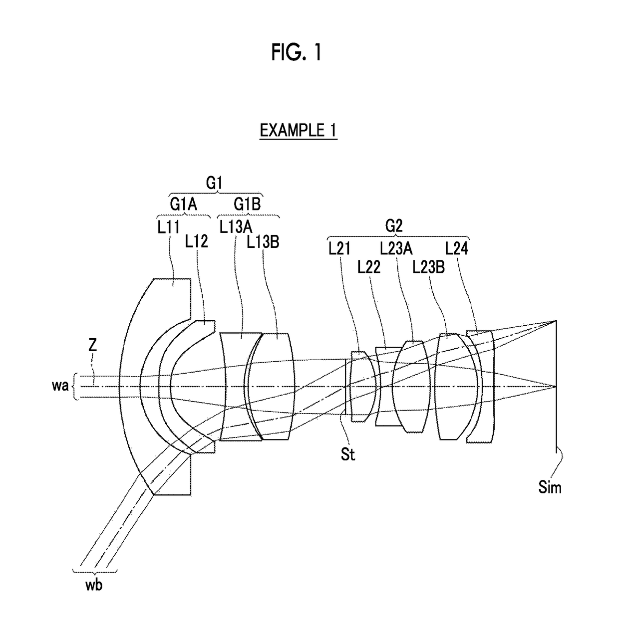
[0045]Hereinafter, embodiments of the present invention will be described with reference to drawings. FIG. 1 is a cross-sectional view illustrating a lens configuration of an imaging lens according to an embodiment of the present invention. The exemplary configuration shown in FIG. 1 is the same as the configuration of the imaging lens of Example 1 to be described later. In FIG. 1, a left side thereof is an object side, and a right side thereof is an image side. In addition, an aperture diaphragm St shown in the drawing does not necessarily indicate its sizes and / or shapes, and indicates a position of the diaphragm on the optical axis Z. Further, on-axis rays wa and rays with a maximum angle of view wb are also shown together.

[0046]As shown inFIG. 1, the imaging lens consists of, in order from the object side, a first lens group G1, an aperture diaphragm St, and a second lens group G2 that has a positive refractive power. With such a configuration, it is possible to minimize an inci...


PUM


Abstract

The imaging lens consists of, in order from an object side: a first lens group G1; a diaphragm; and a second lens group G2 that has a positive refractive power. The first lens group G1 consists of, in order from the object side, a first A lens group G1A that consists of two negative meniscus lenses concave toward an image side, and a first B lens group G1B that consists of only one positive lens or a negative lens and a positive lens. The second lens group G2 consists of, in order from the object side, a biconvex lens, a biconcave lens, one or two biconvex lenses, and a negative meniscus lens that is concave toward the object side. With such a configuration, the imaging lens satisfies predetermined conditional expressions.

Description

CROSS-REFERENCE TO RELATED APPLICATIONS[0001]The present application claims priority under 35 U.S.C. § 119 to Japanese Patent Application No. 2016-043152, filed on Mar. 7, 2016. Each of the above application(s) is hereby expressly incorporated by reference, in its entirety, into the present application.BACKGROUND OF THE INVENTION[0002]1. Field of the Invention[0003]The present invention relates to an imaging lens, which is appropriate for a sensing camera, and an imaging apparatus comprising the imaging lens.[0004]2. Description of the Related Art[0005]Recently, cameras are mounted on a vehicle, and are used to assist a driver to check blind areas such as sides lateral to the driver and / or a rear side or are used to recognize images such as vehicles around own vehicle, pedestrians, and / or obstacles. As an imaging lens usable in such a sensing camera, for example, an imaging lens described in JP2012-108302A to be described later is known. JP2012-108302A discloses a lens system having...

Claims


Application Information

Patent Timeline
Patent Type & Authority Patents(United States)
IPC IPC(8): G02B3/02G02B13/18B60R1/00B60R1/12G02B9/64G02B13/06
CPCG02B13/18B60R1/00B60R1/12G02B13/06G02B9/64B60R2300/802B60R2001/1253
Inventor NODA, TAIGACHO, MICHIO
Owner FUJIFILM CORP
Why Eureka
Try Eureka