Thrust force generation device and aircraft

a technology of thrust force and generation device, which is applied in the direction of efficient propulsion technology, machines/engines, transportation and packaging, etc., can solve the problems of limitation of the diameter of the main body of the engine, limit to the miniaturization of the core engine, etc., and achieve the effect of efficient placemen

Active Publication Date: 2020-08-25
MITSUBISHI HEAVY IND LTD
View PDF36 Cites 7 Cited by
  • Summary
  • Abstract
  • Description
  • Claims
  • Application Information

AI Technical Summary

Benefits of technology

[0023]According to the present invention, in cases where a thrust force generation device includes a thrust unit that generates thrust via fuel and a thrust unit that generates thrust via electric power, both of the thrust units are appropriately and efficiently placed.

Problems solved by technology

However, there is a limit to the miniaturization of the size of the core engine.
Therefore, there is also a limitation on the diameter of the main body of the engine 52.

Method used


Image

  • Thrust force generation device and aircraft
  • Thrust force generation device and aircraft
  • Thrust force generation device and aircraft

Examples


Embodiment Construction

[0031]Hereinafter, a thrust force generation device to be mounted on an aircraft according to an embodiment of the present invention will be described.

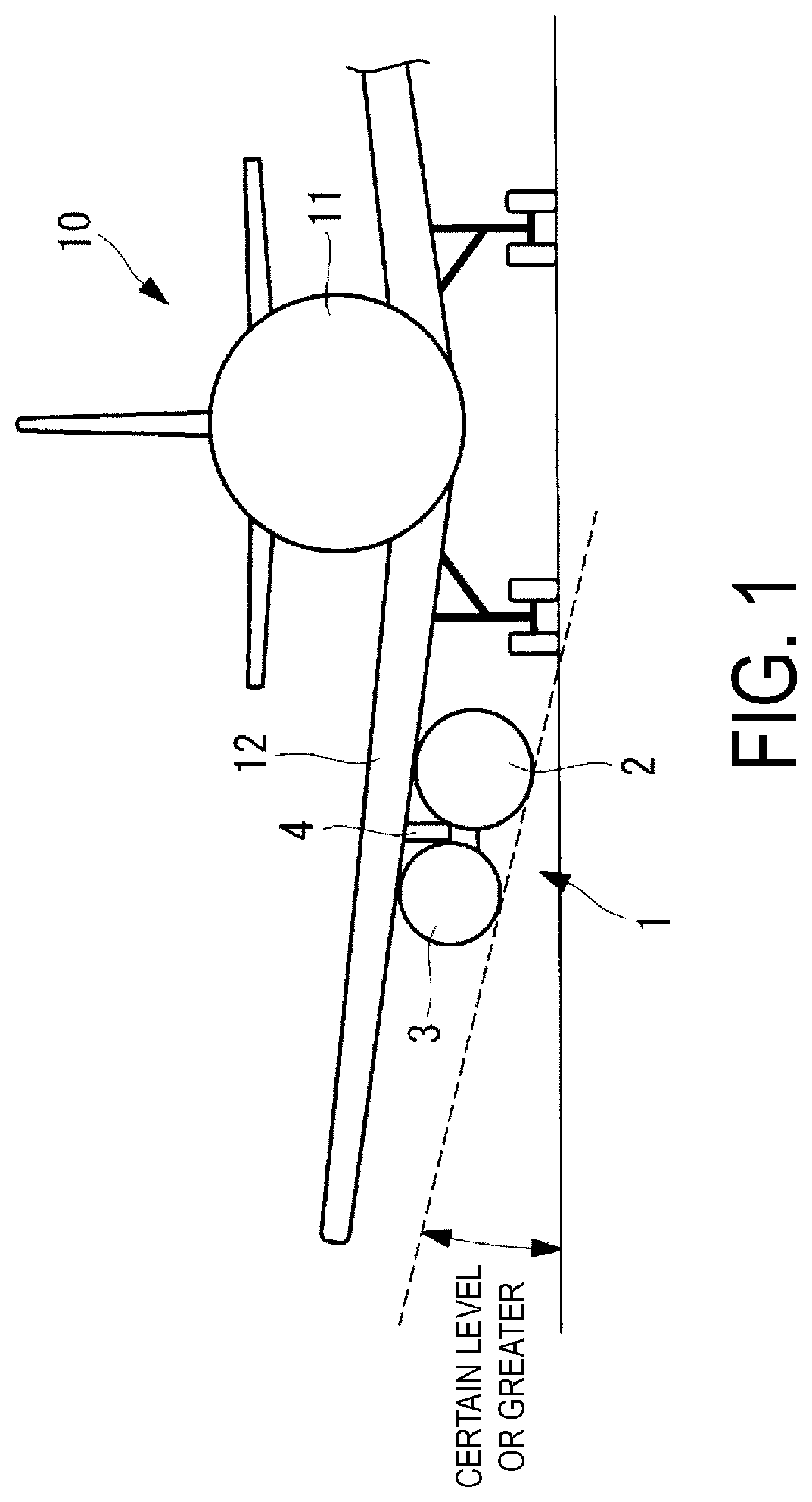
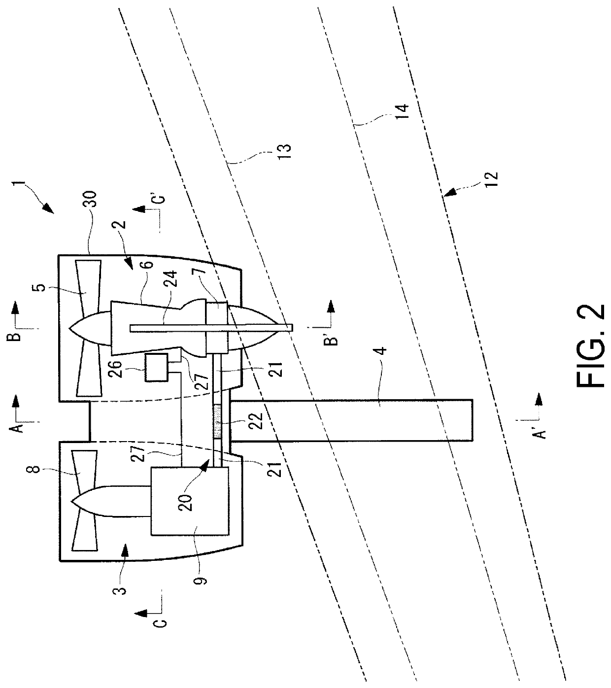
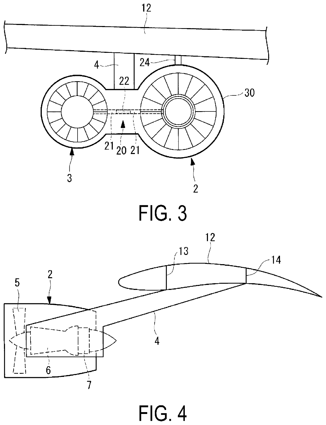
[0032]As illustrated in FIG. 1, a thrust force generation device 1 is, for example, mounted under a main wing 12 of an aircraft 10, and generates thrust force for propelling the aircraft 10. For example, one thrust force generation device 1 is mounted on one of the main wings 12. The thrust force generation device 1 is mounted as a pair on both of the main wings 12. The thrust force generation device 1 includes a turbo fan engine unit 2 and a motor driven fan unit 3. The turbo fan engine unit 2 and the motor driven fan unit 3 are provided in parallel.

[0033]In FIGS. 1 and 2, the turbo fan engine unit 2 is provided on a fuselage 11 side of the aircraft 10, and the motor driven fan unit 3 is provided outward of the turbo fan engine unit 2. The thrust force generation device 1 is mounted on both of the main wings 12 so that the turbo fan ...


PUM


Abstract

The thrust force generation device is provided with: a turbo fan engine unit that includes a generator for generating power using a rotation force of a drive shaft, and that drives a fan placed on the drive shaft using gas produced by combusting fuel; a motor driven fan unit that includes a motor driven by power supplied from the generator, that is placed in parallel with the turbo fan engine unit, and that drives a fan by using the motor; and a conducting unit that connects the generator to the motor, and supplies the power generated by the generator to the motor. The turbo fan engine unit and the motor driven fan unit are integrated with each other, and the conducting unit is placed between the turbo fan engine unit and the motor driven fan unit.

Description

RELATED APPLICATIONS[0001]The present application is National Phase of International Application No. PCT / JP2016 / 055336 filed Feb. 24, 2016, and claims priority from Japanese Application No. 2015-038282, filed Feb. 27, 2015, the disclosure of which is hereby incorporated by reference herein in its entirety.TECHNICAL FIELD[0002]The present invention relates to a thrust force generation device for generating thrust force, that is mounted on an aircraft; and to an aircraft.BACKGROUND ART[0003]With turbo fan engines mounted on aircraft, it is generally known that larger bypass ratios lead to better fuel efficiency. Here, “bypass ratio” is defined as the ratio of the amount of air passing through portions other than the core engine to the amount of air passing through the core engine. However, there is a limit to the miniaturization of the size of the core engine. As such, in order to increase the bypass ratio, the diameter of the engine body must be enlarged to increase the amount of byp...

Claims


Application Information

Patent Timeline
Patent Type & Authority Patents(United States)
IPC IPC(8): B64D27/02B64D27/12B64D27/24B64D27/26F02K5/00B64D27/18F02C6/00F02K3/06F02C7/20F02C3/04
CPCF02C6/00B64D27/12B64D27/26F02C7/20B64D27/24F02K5/00B64D27/18F02K3/06F05D2220/32B64D2027/266B64D2027/026F05D2220/76Y02T50/60Y02T50/40F02C3/04B64D35/04
Inventor TAKAMI, HIKARUYOKOI, YUTO
Owner MITSUBISHI HEAVY IND LTD
Why Eureka
Try Eureka