Imaging apparatus and control method thereof

a technology of imaging apparatus and control method, which is applied in the field of imaging apparatus, can solve the problems of insufficient delay in the timing of the next recording process from the desired timing, and achieve the effect of reducing the power consumption of imaging apparatus

Active Publication Date: 2019-03-05
CANON KK
View PDF5 Cites 0 Cited by
  • Summary
  • Abstract
  • Description
  • Claims
  • Application Information

AI Technical Summary

Benefits of technology

[0007]The present invention provides a technique to more appropriately implement both the reduction of the power consumption of the imaging apparatus and the execution of the recording process at a desired timing in the repeated recording period.
[0012]According to the present invention, both the reduction of the power consumption of the imaging apparatus and the execution of the recording process at a desired timing can be more appropriately implemented in the repeated recording period.

Problems solved by technology

This means that in the case of the technique disclosed in Japanese Patent Application Publication No. 2015-29188, the power consumption of the imaging apparatus may not be sufficiently reduced.
However if the reduction process is performed, regardless whether the time from the current recording process to the next recording process is a predetermined time or less, then the timing of the next recording process may be delayed from the desired timing.

Method used


Image

  • Imaging apparatus and control method thereof
  • Imaging apparatus and control method thereof
  • Imaging apparatus and control method thereof

Examples


Embodiment Construction

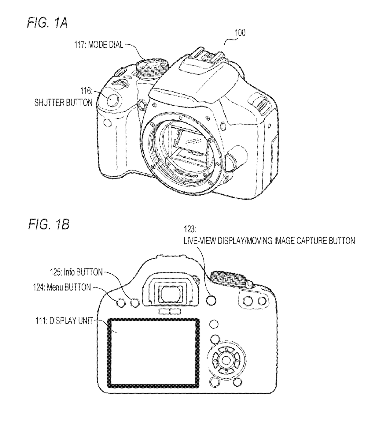
[0020]Embodiments of the present invention will be described. FIGS. 1A and 1B are external views of a digital camera 100, which is an example of an electronic device, FIG. 1A is a perspective view, and FIG. 1B is a rear view.

[0021]A display unit 111 displays a captured image, various information and the like. For example, a combination of a backlight unit and a liquid crystal panel can be used as the display unit 111. A display panel including light-emitting display elements may be used for the display unit 111. In concrete terms, an organic EL display panel, a plasma display panel or the like can be used as the display unit 111.

[0022]A Shutter button 116, a Mode dial 117, a Menu button 124, an Info button 125 and a Live-view display / moving image capture button 123 are operation units used by the user to perform an operation.

[0023]The Shutter button 116 outputs an instruction to prepare imaging, an instruction to execute imaging or the like in accordance with the operation performed...


PUM


Abstract

An imaging apparatus according to the present invention, includes: an imaging unit; a display unit; and a control unit configured, in a period of performing a repeated recording process to perform imaging by the imaging unit at every set interval time and record a captured image in a recording medium, to perform control such that a live-view display on the display unit is turned OFF and driving of the imaging unit is stopped in a case where the interval time is a specific time or longer, and such that the live-view display on the display unit is turned OFF, but the driving of the imaging unit is not stopped in a case where the interval time is less than the specific time.

Description

BACKGROUND OF THE INVENTION[0001]Field of the Invention[0002]The present invention relates to an imaging apparatus and a control method thereof.[0003]Description of the Related Art[0004]A repeated recording process, in which an imaging process and a recording process to record the captured image in a storage unit are performed at every predetermined time, is known as a process (function) of an imaging apparatus. The repeated recording process is called “interval imaging”, “time-lapse imaging” and the like. In the repeated recording process, a captured image is recorded as one frame of a moving image, for example. The moving image generated by the repeated recording process is called a “time-lapse moving image”. According to the repeated recording process, a moving image, in which clouds, scenery and the like change faster than real-time, can be generated as a time-lapse moving image, for example.[0005]A technique of the repeated recording process is disclosed in Japanese Patent Appl...

Claims


Application Information

Patent Timeline
Patent Type & Authority Patents(United States)
IPC IPC(8): H04N5/232
CPCH04N5/23293H04N5/23241H04N23/60H04N23/62H04N23/651H04N23/63H04N5/77
Inventor SHODA, RYOSUKE
Owner CANON KK
Why Eureka
Try Eureka