Imaging lens and imaging apparatus

a technology of imaging apparatus and lens, applied in the direction of optical viewing, vehicle components, instruments, etc., can solve the problem of insufficient correction of various aberrations, and achieve the effect of appropriate and high-quality images

Active Publication Date: 2018-04-24
JIANGXI OFILM OPTICAL CO LTD
View PDF11 Cites 0 Cited by
  • Summary
  • Abstract
  • Description
  • Claims
  • Application Information

AI Technical Summary

Benefits of technology

[0021]Further, the imaging apparatus of the present invention comprises the imaging lens of the present invention. Thus, it is possible to appropriately capture a high quality image with a wide angle of view.

Problems solved by technology

However, correction of various aberrations is not sufficient for the lens system disclosed in JP1993-273459A (JP-H05-273459A).

Method used


Image

  • Imaging lens and imaging apparatus
  • Imaging lens and imaging apparatus
  • Imaging lens and imaging apparatus

Examples


Embodiment Construction

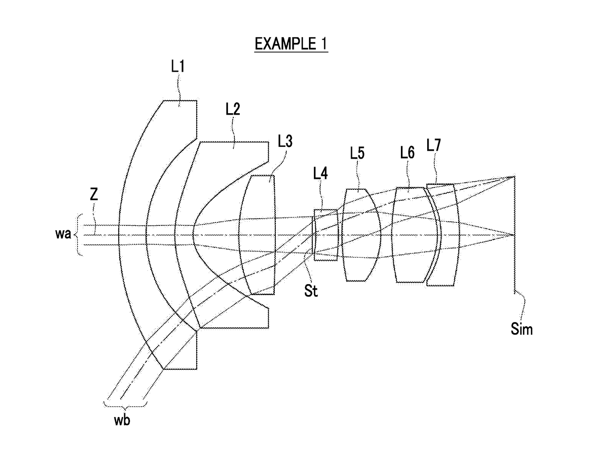
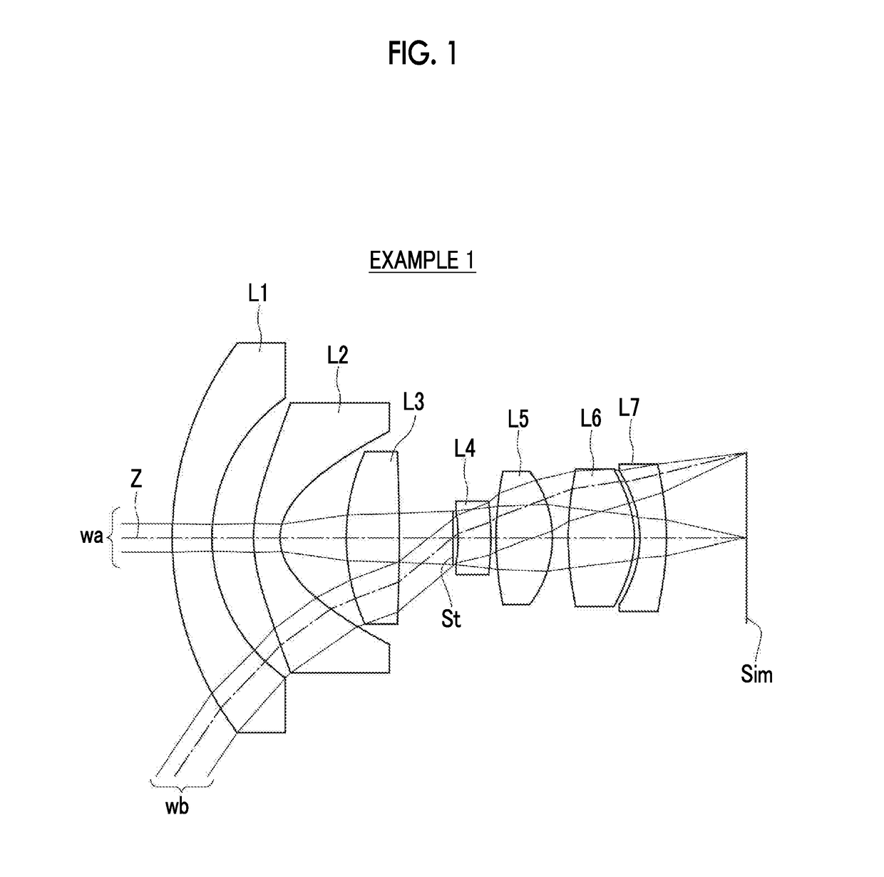
[0035]Hereinafter, embodiments of the present invention will be described with reference to drawings. FIG. 1 is a cross-sectional view illustrating a lens configuration of an imaging lens according to an embodiment of the present invention. The exemplary configuration shown in FIG. 1 is the same as the configuration of the imaging lens of Example 1 to be described later. In FIG. 1, a left side thereof is an object side, and a right side thereof is an image side. In addition, an aperture diaphragm St shown in the drawing does not necessarily indicate its sizes and / or shapes, but indicates a position of the diaphragm on the optical axis Z. Further, on-axis rays wa and rays with a maximum angle of view wb are also shown together.

[0036]As shown in FIG. 1, the imaging lens includes, substantially in order from an object side: a first lens L1 that has a negative refractive power; a second lens L2 that has a negative refractive power; a third lens L3 that has a positive refractive power; a...


PUM


Abstract

Provided are an imaging lens, which is a wide-angle imaging lens and is capable of satisfactorily correcting various aberrations, and an imaging apparatus which includes this imaging lens. The imaging lens consists of, in order from an object side: a first lens L1 that has a negative refractive power; a second lens L2 that has a negative refractive power; a third lens L3 that has a positive refractive power; a fourth lens L4 that has a negative refractive power; a fifth lens L5 that has a positive refractive power; a sixth lens L6 that has a positive refractive power; and a seventh lens L7 that has a negative refractive power. The following conditional expression (1) is satisfied.−2<f / f12<−1.47  (1)

Description

CROSS-REFERENCE TO RELATED APPLICATIONS[0001]The present application claims priority under 35 U.S.C. § 119 to Japanese Patent Application No. 2016-003588, filed on Jan. 12, 2016. Each of the above application(s) is hereby expressly incorporated by reference, in its entirety, into the present application.BACKGROUND OF THE INVENTION[0002]1. Field of the Invention[0003]The present invention relates to an imaging lens that is appropriate for an on-board camera and an imaging apparatus that has the imaging lens.[0004]2. Description of the Related Art[0005]Recently, cameras are mounted on a vehicle, and are used to assist a driver to check blind areas such as sides lateral to the driver and / or a rear side or are used to recognize images such as vehicles around own vehicle, pedestrians, and / or obstacles. As an imaging lens usable in such an on-board camera, for example, an imaging lens described in JP1993-273459A (JP-H05-273459A) to be described later is known. JP1993-273459A (JP-H05-27345...

Claims


Application Information

Patent Timeline
Patent Type & Authority Patents(United States)
IPC IPC(8): G02B13/00G02B9/64G02B27/00B60R1/00
CPCG02B13/0045G02B9/64G02B27/0025G02B13/00B60R2300/10B60R2300/8033B60R1/00G02B13/06G02B13/18
Inventor KITAHARA, YUKAMIYA, TAKESHI
Owner JIANGXI OFILM OPTICAL CO LTD
Why Eureka
Try Eureka