Mounting system for vehicle underride

a technology for underriding and vehicle, which is applied to vehicles with raised loading platforms, vehicle components, transportation items, etc., can solve the problem that the conventional fixed underride is not compatible with the lift, and achieve the effect of reducing clearan

Active Publication Date: 2019-03-05
MAXON INDS INC
View PDF13 Cites 8 Cited by
  • Summary
  • Abstract
  • Description
  • Claims
  • Application Information

AI Technical Summary

Problems solved by technology

As a result, a conventional fixed underride is not compatible with a lift that is stowed under the rear end of the vehicle since the underride interferes with the stowing and unstowing of the lift.

Method used


Image

  • Mounting system for vehicle underride
  • Mounting system for vehicle underride
  • Mounting system for vehicle underride

Examples


Embodiment Construction

[0043]The following description is made for the purpose of illustrating the general principles of the embodiments discloses herein and is not meant to limit the concepts disclosed herein. Further, particular features described herein can be used in combination with other described features in each of the various possible combinations and permutations. Unless otherwise specifically defined herein, all terms are to be given their broadest possible interpretation including meanings implied from the description as well as meanings understood by those skilled in the art and / or as defined in dictionaries, treatises, etc.

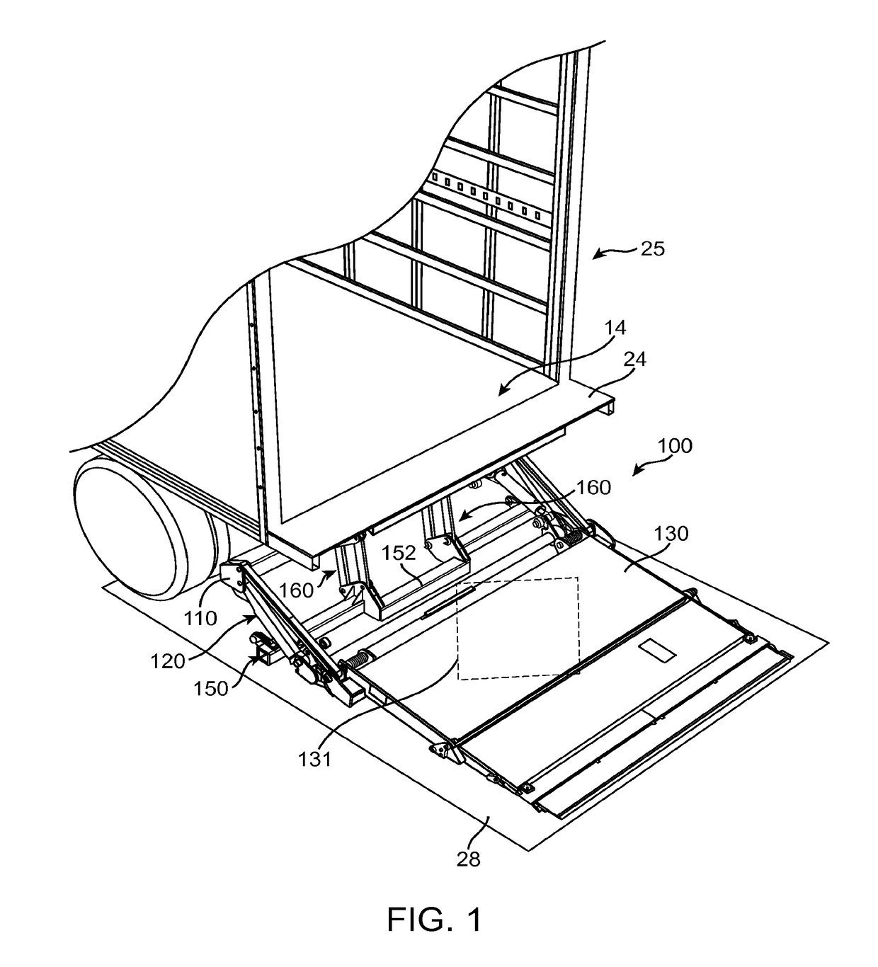
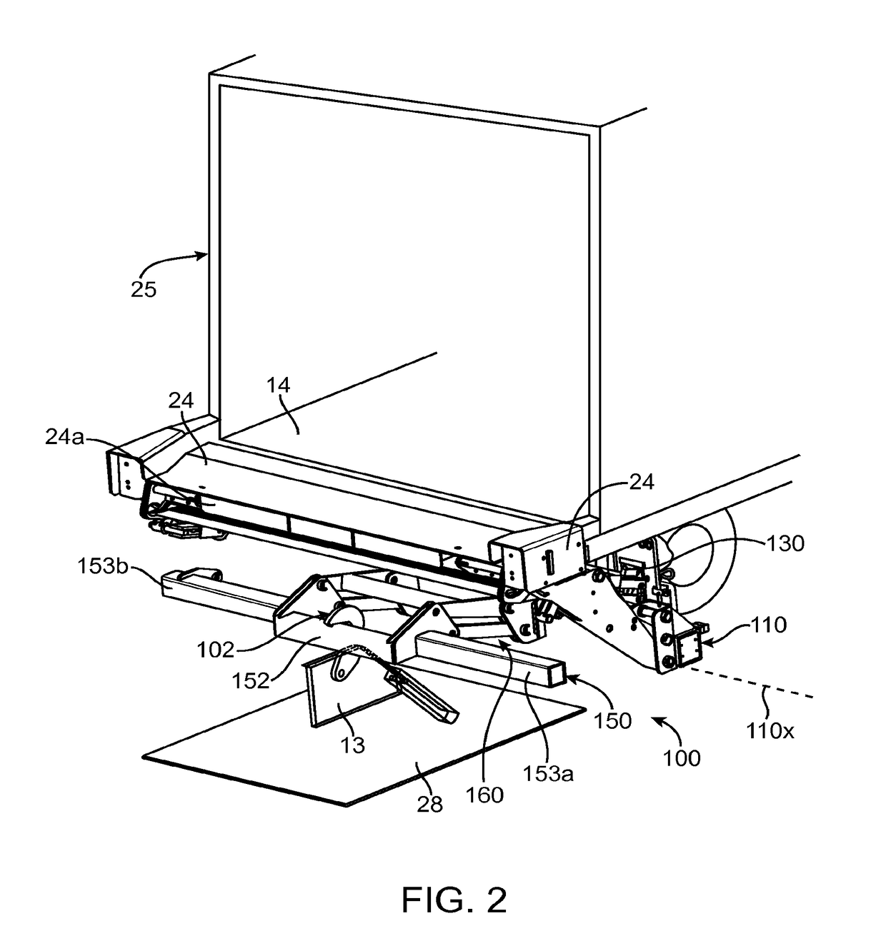
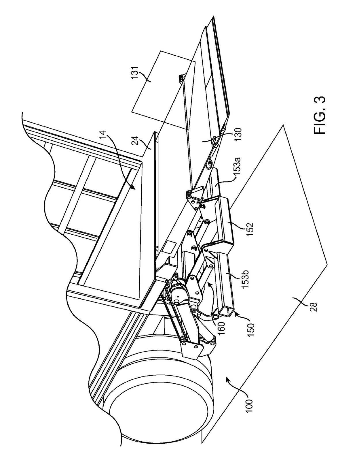
[0044]Embodiments disclosed herein provide a moveable underride system and a mounting system for removably and adjustably mounting the underride system on a structure such as support frame of a vehicle or a lift gate frame. Such moveable underride system may be used with lifts such as stow lifts (tuck under lifts), in one example application. Referring to FIG. 1, according...


PUM


Abstract

A mounting mechanism for mounting an underride system on a structure, comprises a pair of clamping jaws, and a first bracket including a first edge for coupling the underride system thereto. The first bracket further includes a second edge for coupling the pair of clamping jaws thereto. Wherein, the first bracket and the pair of clamping jaws define a jaw opening therebetween configured to receive at least a portion of the structure for removably mounting the underride system on the structure using the mounting mechanism.

Description

CROSS-REFERENCE TO RELATED APPLICATION[0001]This application is a 35 U.S.C § 371 National Stage Entry of International Application No. PCT / US2014 / 068890, filed Dec. 5, 2014, which claims priority benefit of U.S. Provisional Patent Application Ser. No. 61 / 914,296, filed Dec. 10, 2013, both of which are incorporated herein by reference.FIELD OF THE INVENTION[0002]The embodiments disclosed herein relate generally to underride systems, and in particular to underride systems for vehicles with lift gates.DESCRIPTION OF RELATED ART[0003]Rear impact guards, or commonly known as underrides, are used to reduce the chance of following vehicles from driving underneath the bed of a vehicle such as a truck or a trailer. Conventionally, trucks have a fixed horizontal underride installed below the vehicle bed via vertical beams. The fixed underride is positioned under the end of the vehicle close to or flush with a plane of the rear end of the vehicle. The vertical height between the underride and ...

Claims


Application Information

Patent Timeline
Patent Type & Authority Patents(United States)
IPC IPC(8): B60P1/44B60R19/56
CPCB60P1/4485B60R19/56B60P1/445B60P1/44
Inventor ABLABUTYAN, KARAPETGASPARIAN, AKOP
Owner MAXON INDS INC
Why Eureka
Try Eureka