
Printing machine

a printing machine and control technology, applied in the direction of digital output to print units, instruments, computing, etc., can solve the problems of user discomfort about the finish, productivity and quality of printing, etc., and achieve the effect of lowering productivity and quality in printing and not to the utmost exten

Active Publication Date: 2019-03-05
RISO KAGAKU CORP
View PDF5 Cites 1 Cited by
  • Summary
  • Abstract
  • Description
  • Claims
  • Application Information

AI Technical Summary

Benefits of technology

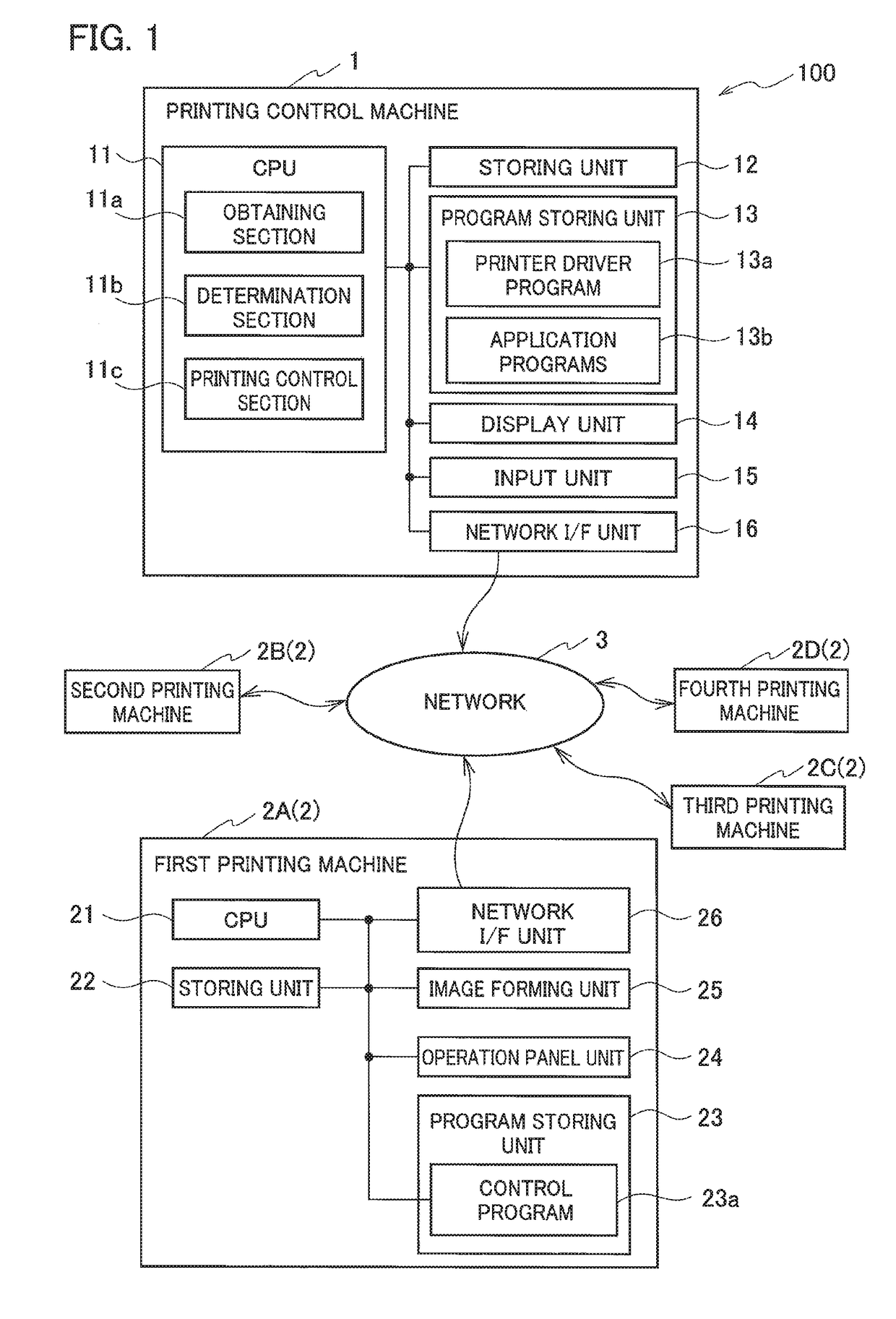
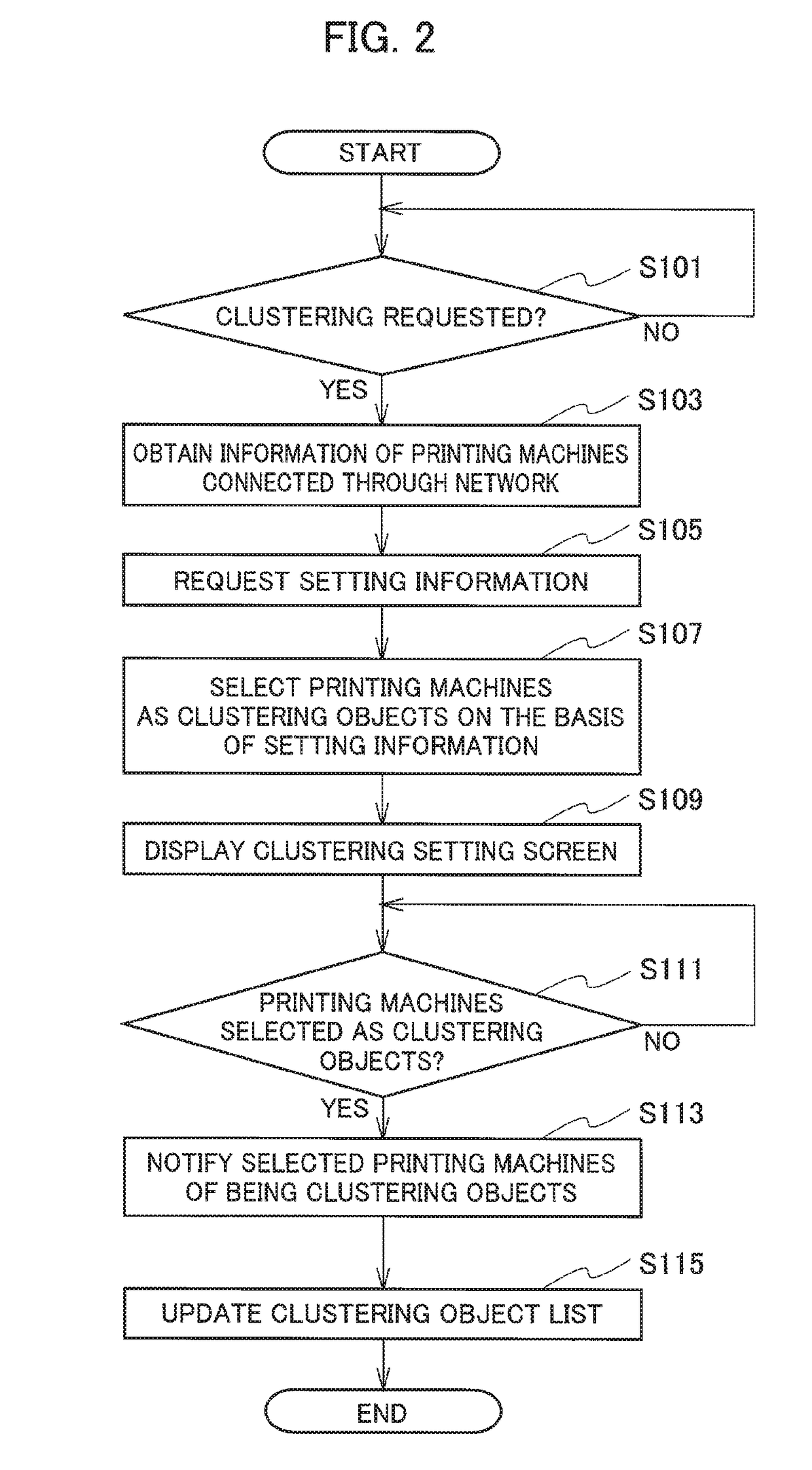
[0007]The present invention is made in view of the above-described problem. An object of the present invention is to provide a printing control machine that makes printing machines, which are connected to the printing control machine through a network and configure a cluster, perform printing without lowering quality in the printing.
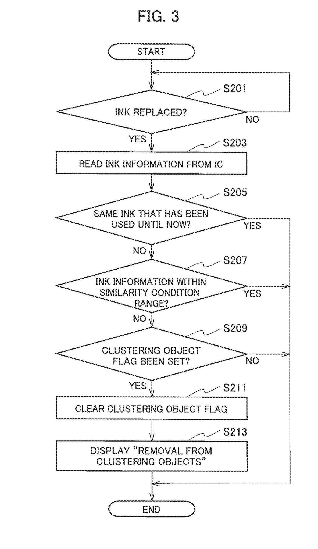
[0013]According to the first aspect of the printing machine in the present invention, the processor obtains the expendable supply information regarding an mounted expendable supply from each of the plurality of printing machines, determines whether or not each of the plurality of printing machines is within the similarity condition range based on the expendable supply information, and allocates the printing job to printing machines determined to be within the similarity condition range to make the determined printing machines perform printing. This prevents a user from having an uncomfortable feeling about the finish when all the prints are brought together.
[0016]When a cluster is configured with two or more printing machines connected to the printing control machine through the network, it is therefore possible to perform printing without lowering productivity and quality in the printing.
[0020]For this reason, when a printing machine being out of the similarity condition range is included in the clustering objects, it is possible to perform printing processing without lowering productivity to the utmost.
[0021]According to the fifth aspect of the printing machine in the present invention, when a cluster is configured with two or more printing machines connected to the printing control machine through the network, printing is performed without lowering productivity and quality in the printing.

Problems solved by technology

This grouping thus does not consider properties of the image forming machines, and may have a problem in productivity and quality in printing.
When all the prints are brought together, a user has an uncomfortable feeling about the finish.

Method used


Image

  • Printing machine
  • Printing machine
  • Printing machine

Examples


Embodiment Construction

[0029]A printing control machine according to an exemplary embodiment of the present invention will be described below with reference to the accompanying drawings. The printing control machine according to the exemplary embodiment presents an example of an apparatus and the like for realizing the technical concept of the present invention. The technical concept of the present invention regarding the arrangement and the like of various structural components is not limited to the embodiment. Various modifications can be made in the technical concept of the present invention within the scope of claims.

[0030]FIG. 1 is a diagram illustrating a configuration of a printing system 100 according to an exemplary embodiment of the present invention. The printing system 100 includes a printing control machine 1 and a plurality of printing machines 2.

[0031]As shown in FIG. 1, the printing control machine 1 is connected to a first printing machine 2A, a second printing machine 2B, a third printin...


PUM


Abstract

A printing control machine includes an obtaining section, a determination section, and a printing control section. The obtaining section obtains from each of a plurality of printing machines, ink information regarding an ink mounted to the each printing machine. The determination section determines whether or not each of the plurality of printing machines is within a similarity condition range on the basis of the ink information obtained by the obtaining section. The printing control section allocates a printing job to printing machines determined to be within the similarity condition range to make the determined printing machines perform printing.

Description

CROSS REFERENCE TO RELATED APPLICATION[0001]This application claims benefit of priority under 35 U.S.C. § 119 to Japanese Patent Application No. 2016-246615, filed on Dec. 20, 2016, the entire contents of which are incorporated by reference herein.BACKGROUND OF THE INVENTION1. Field of the Invention[0002]The present invention relates to a printing control machine that makes printing machines, which are connected to the printing control machine through a network and configure a cluster, perform printing without lowering quality in printing.2. Description of the Related Art[0003]In recent years, many offices employ a printing system in which a computer and a plurality of printing machines are connected to each other through a network to configure a cluster, and the printing machines perform printing in distributed processing for one printing job sent from the computer.[0004]Patent Literature 1 (Japanese Patent Application Laid-Open No. 2015-210686) discloses a technique regarding an i...

Claims


Application Information

Patent Timeline
Patent Type & Authority Patents(United States)
IPC IPC(8): G06F3/12B41J2/175
CPCG06F3/1296B41J2/17546G06F3/124G06F3/1208G06F3/1215G06F3/1293G06F3/1258G06F3/1261G06F3/1285G06F3/1286G06F3/1291G06F3/1229
Inventor TAKATA, ATSUSHI
Owner RISO KAGAKU CORP
Learn More