
Apparatus and method for high speed ultrasonic data acquisition

a high-speed ultrasonic data and apparatus technology, applied in the field of ultrasonic diagnostic systems, can solve the problems of inability to further analyze and process high-speed ultrasonic data within the ultrasonic diagnostic system per se, and the flat cable is not adaptable to the transfer of high-speed signals

Inactive Publication Date: 2008-05-15
SHENZHEN MINDRAY BIO MEDICAL ELECTRONICS CO LTD
View PDF15 Cites 26 Cited by
  • Summary
  • Abstract
  • Description
  • Claims
  • Application Information

AI Technical Summary

Benefits of technology

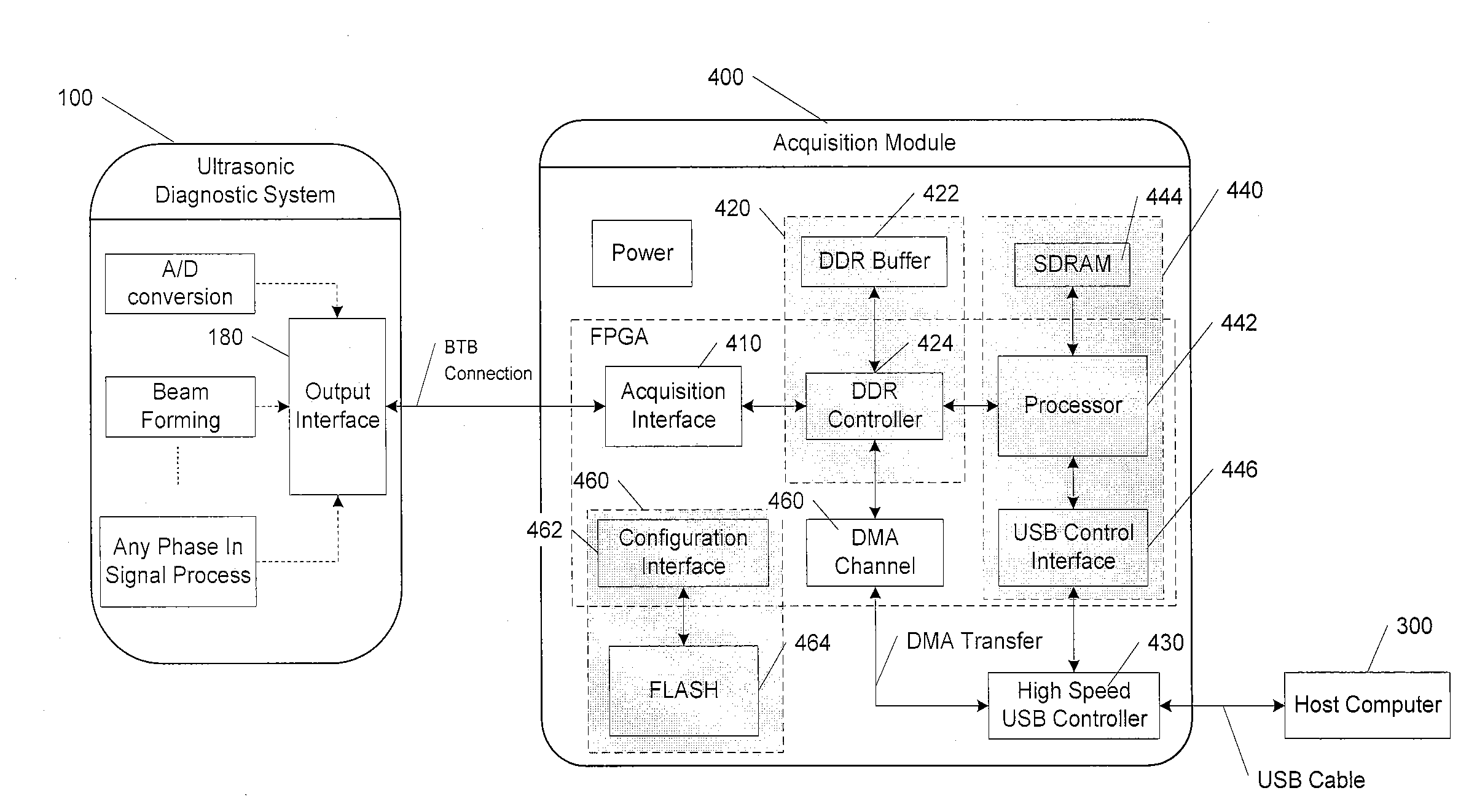
The present invention provides an apparatus and method for ultrasonic data acquisition. The apparatus is directly connected to an ultrasonic diagnostic system and can transfer high-speed ultrasonic data to a host computer without impacting the normal operation of the ultrasonic diagnostic system. The apparatus includes an acquisition interface for obtaining ultrasonic data, a large-capacity buffer for holding the data, and a high-speed USB controller for transferring the data to the host computer. The apparatus can be flexibly configured and includes a DMA channel unit, a DDR controller, and an embedded processor. The method involves using the apparatus to acquire ultrasonic data and transfer it to the host computer in real-time or non-real-time. The technical effect of the invention is to enable high-speed data transfer without impacting the ultrasonic diagnostic system and provide sufficient memory space to hold a large amount of ultrasonic data.

Problems solved by technology

In general, however, the Ultrasonic Diagnostic System itself has limited capability in data processing, especially in data processing speed.
Thus, it is hard to further analyze and process the high-speed ultrasonic data within the Ultrasonic Diagnostic System per se.
However, it has been noted that the flat cable is not adaptable to the transfer of high-speed signals, because the interference between the adjacent lines has significant impact on the signal quality, which further causes the Ultrasonic Diagnostic System to be off-normal.
Thus, the casing of the Ultrasonic Diagnostic System is normally unclosed, and thereby it might have a negative effect on the normal operation of the system.
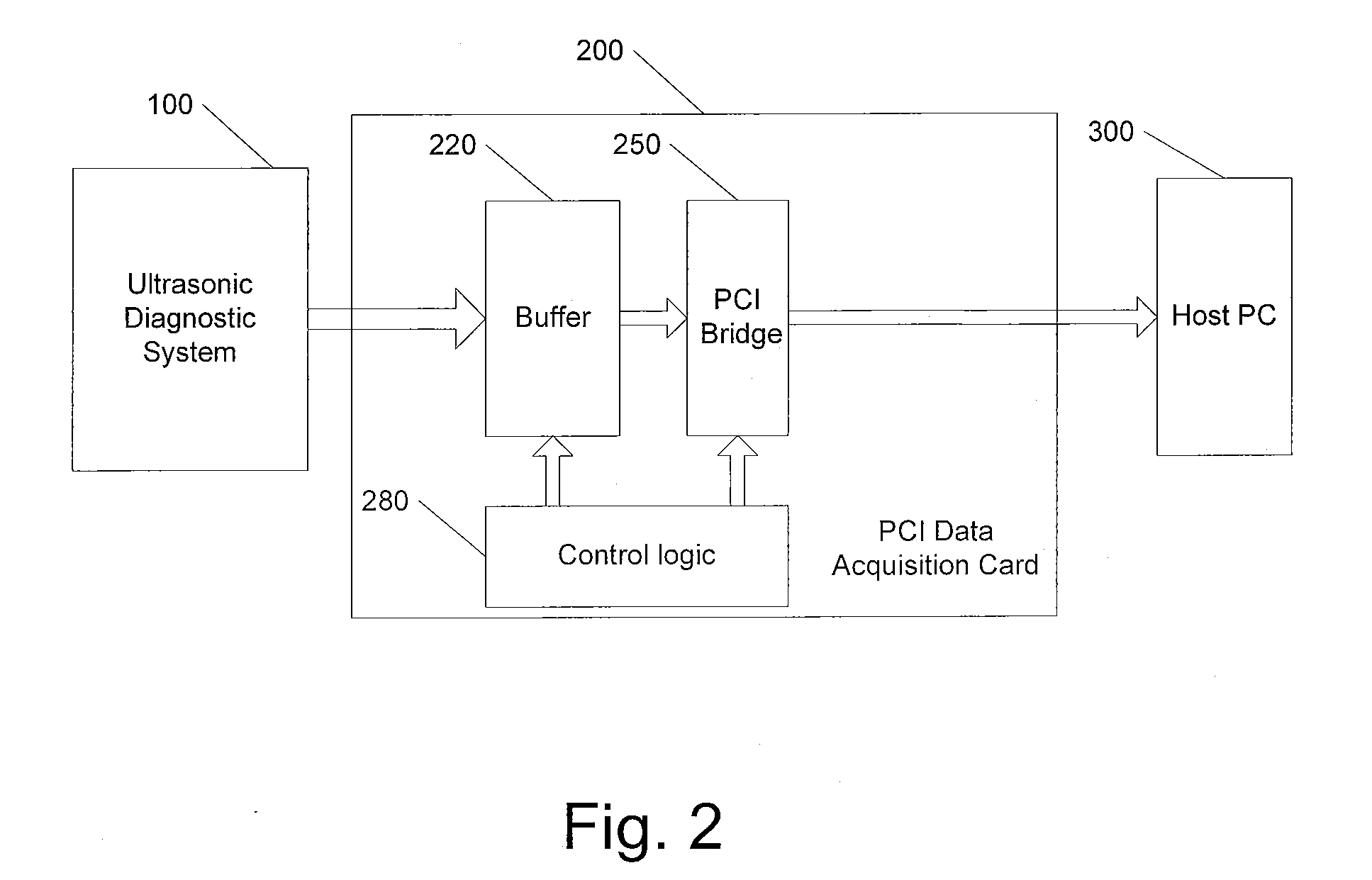
Additionally, PCI data acquisition card is required to be plugged into the inside of the host computer, which is very inconvenient and goes against the mobile data acquisition.
For this reason, when the high-speed ultrasonic data has a bandwidth greater than that of PCI bus, part of the ultrasonic data are very likely to be lost, and thus real time imaging would be interrupted.

Method used


Image

  • Apparatus and method for high speed ultrasonic data acquisition
  • Apparatus and method for high speed ultrasonic data acquisition
  • Apparatus and method for high speed ultrasonic data acquisition

Examples


Embodiment Construction

[0025]In the following, various preferred embodiments will be described in detail in connection with the appended drawings.

[0026]FIG. 3 shows an ultrasonic data acquisition module 400 according to an embodiment of present invention, which is connected between a conventional Ultrasonic Diagnostic System 100 and a host computer 300.

[0027]In FIG. 3, the conventional Ultrasonic Diagnostic System 100 comprises an A / D conversion circuit, a beam forming circuit, other optional signal processing circuits, and an output interface 180 coupled to ultrasonic data acquisition module 400 of present invention (hereinafter referred to as “acquisition module 400” for short). As shown in FIG. 3, the acquisition module 400, on the one hand, is provided within the Ultrasonic Diagnostic System 100, preferably plugged into a preset socket or slot on the main board of the Ultrasonic Diagnostic System 100. On the other hand, the acquisition module 400 is coupled to the host computer 300 via a USB interface...


PUM


Abstract

The present invention provides an apparatus and method for high-speed ultrasonic data acquisition. The apparatus is arranged within an ultrasonic detection system, and comprises: an acquisition interface, coupled to the ultrasonic detection system, for obtaining ultrasonic data from the ultrasonic detection system; a large-capacity buffer for holding the ultrasonic data obtained by the acquisition interface; a high-speed USB (Universal Serial Bus) controller, for transferring the ultrasonic data in the large-capacity buffer to the host computer via a USB interface.

Description

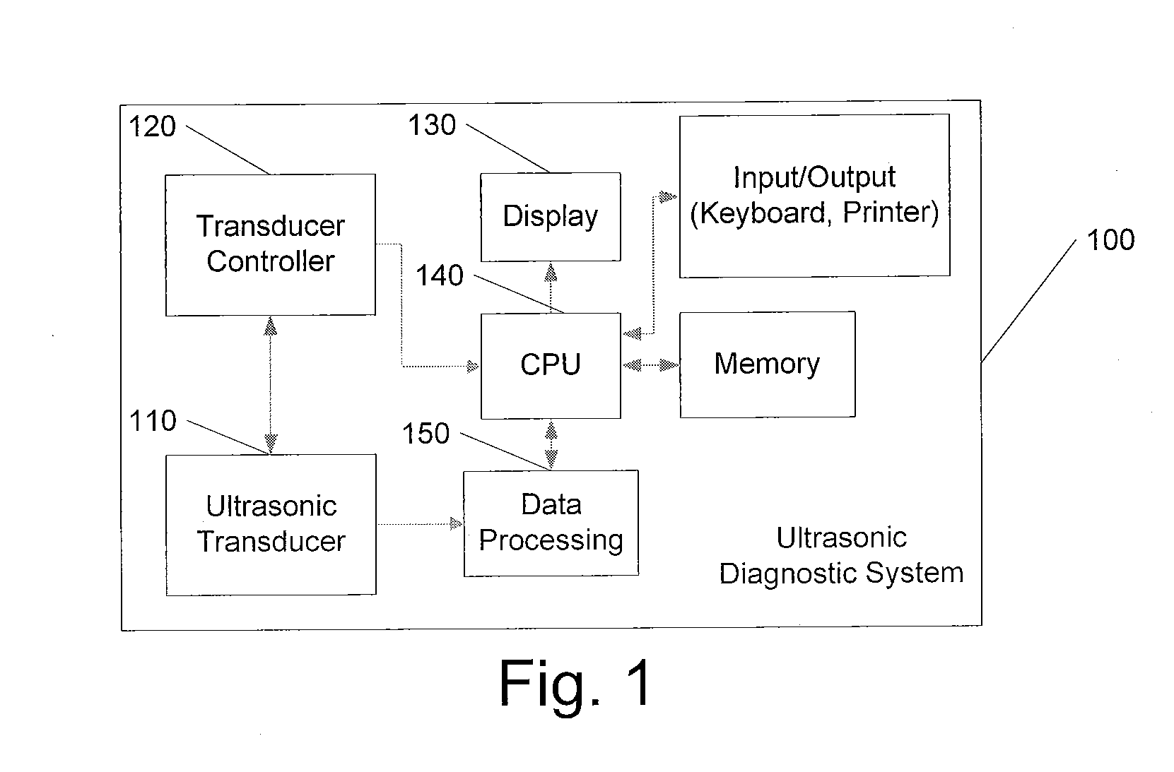
FIELD OF INVENTION[0001]The present invention relates to an Ultrasonic Diagnostic System and the method thereof, especially to an apparatus and method for ultrasonic data acquisition, with which ultrasonic data from an Ultrasonic Diagnostic System can be transferred to a Host computer in high speed.BACKGROUND OF THE INVENTION[0002]Recently, ultrasonic systems have gained popularity for medical diagnosis because they are capable of providing accurate and real time imaging of organs, tissues or blood flow of the body in a non-invasive manner. The ultrasonic system used for medical diagnosis is referred to as ”Ultrasonic Diagnostic System”.[0003]FIG. 1 is a block diagram illustrating a structure of a conventional Ultrasonic Diagnostic System. As shown in FIG. 1, the Ultrasonic Diagnostic System 100 comprises an ultrasonic transducer 110 and a transducer controller 120, both of which are controlled by a CPU 140. The ultrasonic transducer 110 transmits pulses to generate ultrasound waves...

Claims


Application Information

Patent Timeline
Patent Type & Authority Applications(United States)
IPC IPC(8): G06F13/28G06F13/00
CPCG01S7/52017
Inventor HE, XUJINWANG, ZHEYUAN, MAN
Owner SHENZHEN MINDRAY BIO MEDICAL ELECTRONICS CO LTD
Learn More