Card edge connector with anti-wicking structure

a card edge connector and anti-wicking technology, applied in the direction of electrically conductive connections, coupling device connections, computer periphery connectors, etc., can solve the problems of unfavorable capillary attraction, unfavorable capillary attraction, and disclosed anti-wicking structures, so as to efficiently restrict up-and-down movement and prevent capillary attraction

Active Publication Date: 2019-03-19
FOXCONN INTERCONNECT TECH LTD
View PDF8 Cites 0 Cited by
  • Summary
  • Abstract
  • Description
  • Claims
  • Application Information

AI Technical Summary

Benefits of technology

[0004]To achieve the above desire, a card edge connector includes an elongated insulative housing extending along a longitudinal direction, and a row of first contacts arranged with one another along the longitudinal direction. The insulative housing includes a main body composed of two opposite first side wall and second side wall with a central slot therebetween. The first side wall forms a plurality of first passageway. The first side wall forms a mounting face opposite to the central slot. The first contact includes a first retaining section secured to the first side wall, a first resilient arm extending from an upper part of the first retaining section and extending into the central slot to form a contacting section, and a first tail section extending from a lower part of the first retaining section and out of the mounting face. The first resilient arm defines a first end adjacent to the first retaining section and right above the first tail section, and a second end adjacent to the contacting section wherein a gap between the interior surface of the first passageway and the first end in the longitudinal direction is larger than that between the interior surface of the first passageway and the second end. The gap around the second end is essentially slightly larger than a thickness of the first contact for efficiently restricting up-and-down movement of the contacting section with regard to the first passageway, and the gap around the first end is essentially relatively significantly larger than the thickness of the first contact for efficiently preventing capillary attraction with regard to the melted solder during soldering the first tail section upon the printed circuit board.

Problems solved by technology

Therefore, the anti-wicking structure disclosed in the aforementioned CN 603631820U is not efficiently fit for the card edge connector.

Method used


Image

  • Card edge connector with anti-wicking structure
  • Card edge connector with anti-wicking structure
  • Card edge connector with anti-wicking structure

Examples


Embodiment Construction

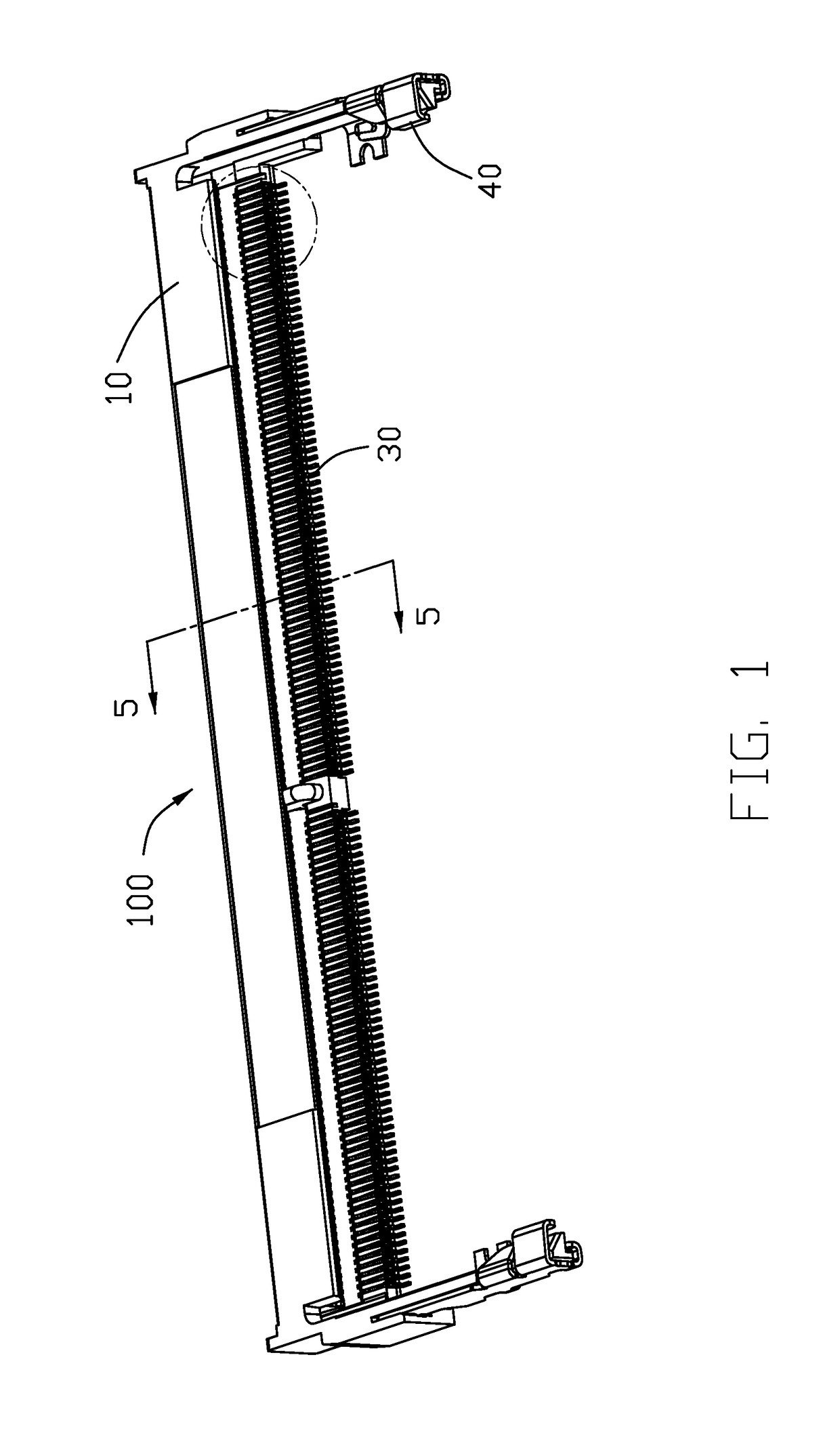
[0014]Reference will now be made in detail to the embodiments of the present disclosure. Referring to FIGS. 1-9 an electrical card edge connector assembly includes an electrical card edge connector 100 for mounting to a printed circuit board (not shown) and for mating with a memory module (not shown).

[0015]The connector 100 includes an elongated insulative housing 10 extending along a longitudinal direction, two rows of terminals disposed in the housing 1, and a pair of metal parts 40. The housing 1 includes a main body 12 extending along a longitudinal direction, and a pair of latching arms 16 forwardly extending, from two opposite ends of the main body 12, in a front-to-back direction perpendicular to the longitudinal direction. The metal part 40 includes a first metal piece 41 is secured to the corresponding latching arm 16 for mounting to the printed circuit board, and a second metal piece 42 is secured to the corresponding latching arm 16 and cooperates with latching arm 16 to ...


PUM


Abstract

A card edge connector forms a plurality of passageways in the elongated housing to receive the corresponding contacts. Each contact has a retaining section secured to the housing, a resilient arm extending from an upper part of the retaining section with a contacting section exposed in the central slot, a soldering section extending from a lower part of the retaining section and out of the housing. A width of the passageway around the contacting section in the longitudinal direction is smaller than that around the soldering section.

Description

BACKGROUND OF THE DISCLOSURE1. Field of the Disclosure[0001]The invention is related to an electrical connector, and particularly to the card edge connector equipped with anti-wicking structures of the housing.2. Description of Related Arts[0002]China Utility Patent No. CN 202856007U discloses a card edge connector including an insulative elongated housing, a plurality of terminals and a pair of latches at two opposite ends thereof. The housing forms a plurality of passageways in a slit form to receive the blanking type terminals therein, respectively. Because the interior surface of the passageway is so close to the side surfaces of the corresponding terminal, the capillary attraction may occur between the solder material and the terminal when the terminal is soldered upon the printed circuit board. China Utility Patent No. CN 203631820U discloses a modular jack connector with an upward facing cavity, as an anti-wicking structure, formed in the upward face of the footer insulator t...

Claims


Application Information

Patent Timeline
Patent Type & Authority Patents(United States)
IPC IPC(8): H01R12/52H01R13/05H01R13/506H01R4/02H01R12/70H01R12/71H01R12/83
CPCH01R12/52H01R4/028H01R12/707H01R13/506H01R13/055H01R2201/06H01R12/712H01R12/83
Inventor SUN, WEI-GUO
Owner FOXCONN INTERCONNECT TECH LTD
Why Eureka
Try Eureka