Combined fan and motor

a technology of combined fans and motors, applied in the direction of efficient propulsion technologies, vertical landing/take-off aircraft, power plant types, etc., can solve the problem that existing types of lift fans may not be attractive to such aircra

Active Publication Date: 2019-04-16
WISK AERO LLC
View PDF19 Cites 20 Cited by
  • Summary
  • Abstract
  • Description
  • Claims
  • Application Information

AI Technical Summary

Problems solved by technology

Existing types of lift fans may not be attractive for such aircraft because they are not aerodynamic enough, they weight too much, and / or they consume too much power.

Method used


Image

  • Combined fan and motor
  • Combined fan and motor
  • Combined fan and motor

Examples


Embodiment Construction

[0011]The invention can be implemented in numerous ways, including as a process; an apparatus; a system; a composition of matter; a computer program product embodied on a computer readable storage medium; and / or a processor, such as a processor configured to execute instructions stored on and / or provided by a memory coupled to the processor. In this specification, these implementations, or any other form that the invention may take, may be referred to as techniques. In general, the order of the steps of disclosed processes may be altered within the scope of the invention. Unless stated otherwise, a component such as a processor or a memory described as being configured to perform a task may be implemented as a general component that is temporarily configured to perform the task at a given time or a specific component that is manufactured to perform the task. As used herein, the term ‘processor’ refers to one or more devices, circuits, and / or processing cores configured to process da...


PUM


Abstract

A lift fan includes a stator which is configured to output a magnetic field. The lift fan also includes a first housing which in turn includes a blade, a second housing, and a magnet array. The magnet array is coupled to either the first housing or the second housing and the housing, which is coupled to the magnet array, rotates in response to the magnet array responding magnetically to the magnetic field output by the stator.

Description

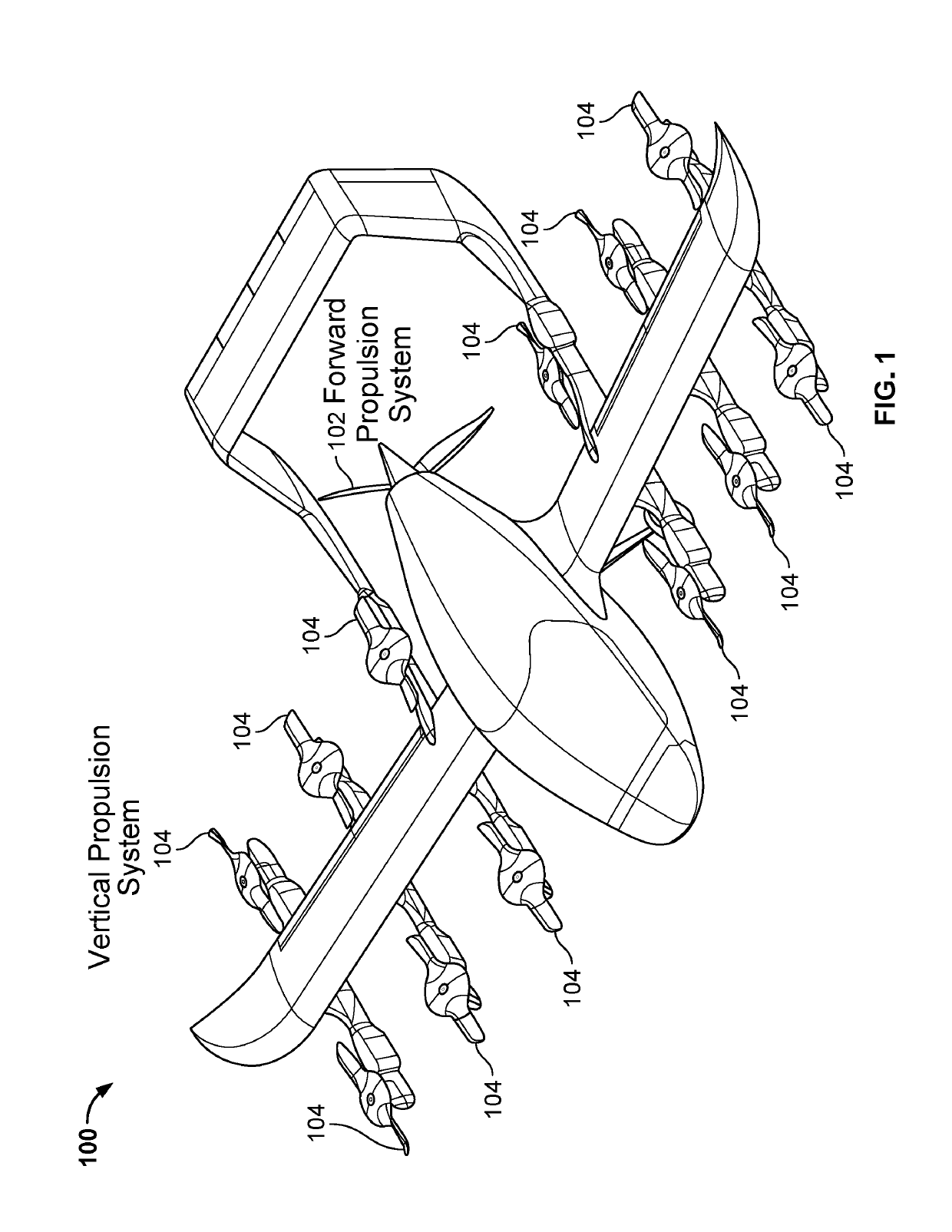
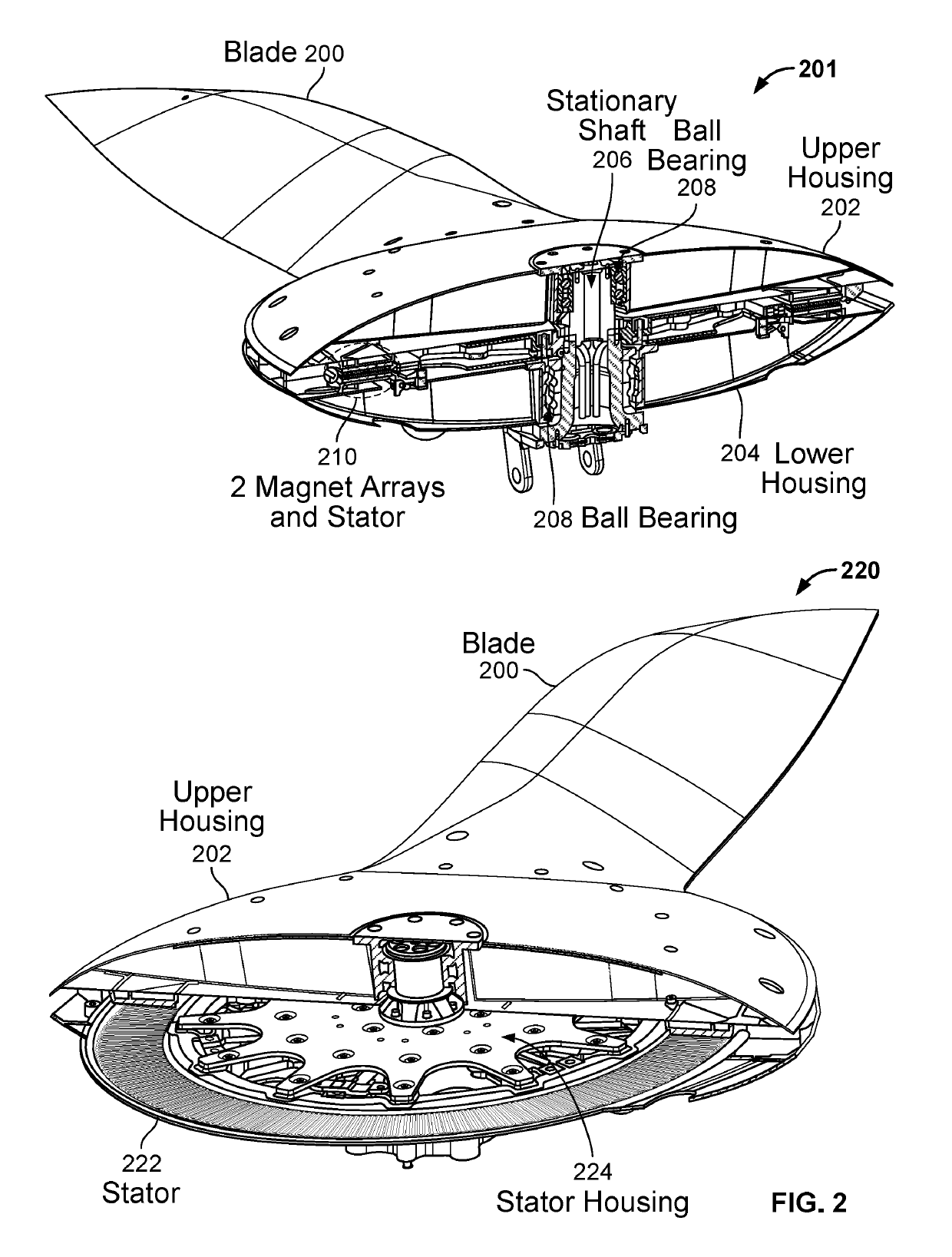
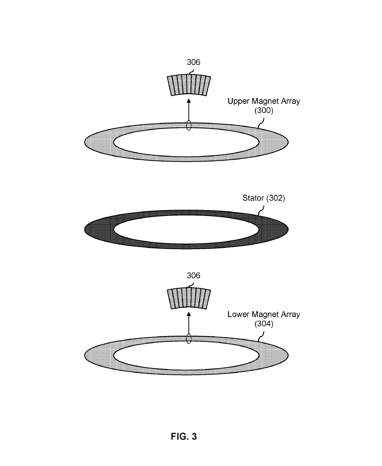
BACKGROUND OF THE INVENTION[0001]New types of aircraft are being developed which are battery powered. Existing types of lift fans may not be attractive for such aircraft because they are not aerodynamic enough, they weight too much, and / or they consume too much power. New types of lift fans which better suited to meet the needs of such new aircraft would be desirable.BRIEF DESCRIPTION OF THE DRAWINGS[0002]Various embodiments of the invention are disclosed in the following detailed description and the accompanying drawings.[0003]FIG. 1 is a diagram illustrating an embodiment of a multicopter which uses a combined fan and motor.[0004]FIG. 2 is a diagram illustrating an embodiment of a combined fan and motor.[0005]FIG. 3 is a diagram illustrating an embodiment of an upper magnet array, a lower magnet array, and a stator associated.[0006]FIG. 4 is a diagram illustrating an embodiment of surface-mounted and embedded magnet arrays.[0007]FIG. 5 is a diagram illustrating an embodiment of an...

Claims


Application Information

Patent Timeline
Patent Type & Authority Patents(United States)
IPC IPC(8): B64C11/18B64D35/06B64C27/28B64C3/26B64C11/16B64C29/00B64C27/82B64C27/22B64D35/04B64C27/72
CPCB64C11/18B64C3/26B64C27/28B64D35/06B64D35/04B64C27/22B64C29/0075B64C2027/7277B64C2027/8254B64C11/16B64C11/02B64C11/20B64C27/32B64C29/0025B64D27/24B64D35/02H02K21/24H02K7/14Y02T50/60B64C11/28
Inventor LONG, GEOFFREY ALAN
Owner WISK AERO LLC
Why Eureka
Try Eureka