Floating, yawing spar current/tidal turbine

a tidal turbine and current technology, applied in the field of turbine systems, can solve the problems of inability to operate, rigidly mounted structures require greater structural margins, and currents are often relatively turbulent, so as to and reduce the risk of tidal turbulen

Active Publication Date: 2019-05-21
AQUANTIS
View PDF7 Cites 1 Cited by
  • Summary
  • Abstract
  • Description
  • Claims
  • Application Information

AI Technical Summary

Benefits of technology

[0018]This present invention has significant advantages over existing tidal current turbines. First, currents are often relatively turbulent and flow faster closer toward the surface. Certain tidal turbines are mounted rigidly on the seabed and they are not able to operate in the higher, more energetic flow speeds near the surface. Furthermore, rigidly mounted structures require greater structural margins, which have significantly higher costs. The yawing spar turbine platform of the present invention floats with a portion of the spar above the water surface, but is resiliently stationed by mooring cables and can therefore flex to mitigate higher loads from wave turbulence and unusually higher speeds in the flow. Second, the cost of seabed mounted turbines can be extremely high due to the massive structure and foundation required, short windows of nil flow (still water) and the complexities and costs of underwater construction requiring specialized ships and cranes. The spar turbine of the present invention utilizes conventional anchoring systems providing substantial cost savings compared to seabed mounted. Third, the turbine of the present invention captures more energy in the tidal flow by passively adjusting its operating depth by means of rotor drag. As the tides change direction, the flow slows and virtually stops, then the counter flow starts to increase. With minimum flow the spar turbine is closer to the surface, since the rotor drag is less and the machine captures whatever energy is yielded in that flow. As the flow velocity increases, the rotor drag increases, and the mooring to the seabed creates a downward force which causes the spar buoy to reach a depth where the downward force of the moored rotor drag equals the upward force of the platform buoyancy. Higher flow speed results in more rotor drag driving the buoyant spar deeper. In this manner, the turbine operates more of the time in its design capacity range, than a turbine vertically fixed in the flow. Fourth, in certain prior art, a vessel on the surface rotates multiple arms with turbines, down below the surface to a vertical rotor operating position. Since this vessel operates on the surface this precludes adjusting the rotor depth to the current velocity for gains in turbine power production. The surface vessel is also subjected to extreme forces of high seas and turbulent wave action. The yawing spar turbine of the present invention has the special properties of a spar buoy where small ocean surface area is penetrated by the cylindrical spar structure, ideal for minimizing wave loading. The small surface area coupled with the mass of the spar turbine results in minimal heave of the system and stresses on the structure in destructive wave environments, allowing for a lighter structure with lower costs.

Problems solved by technology

First, currents are often relatively turbulent and flow faster closer toward the surface.
Certain tidal turbines are mounted rigidly on the seabed and they are not able to operate in the higher, more energetic flow speeds near the surface.
Furthermore, rigidly mounted structures require greater structural margins, which have significantly higher costs.
Second, the cost of seabed mounted turbines can be extremely high due to the massive structure and foundation required, short windows of nil flow (still water) and the complexities and costs of underwater construction requiring specialized ships and cranes.
Higher flow speed results in more rotor drag driving the buoyant spar deeper.
The surface vessel is also subjected to extreme forces of high seas and turbulent wave action.

Method used


Image

  • Floating, yawing spar current/tidal turbine
  • Floating, yawing spar current/tidal turbine
  • Floating, yawing spar current/tidal turbine

Examples


Embodiment Construction

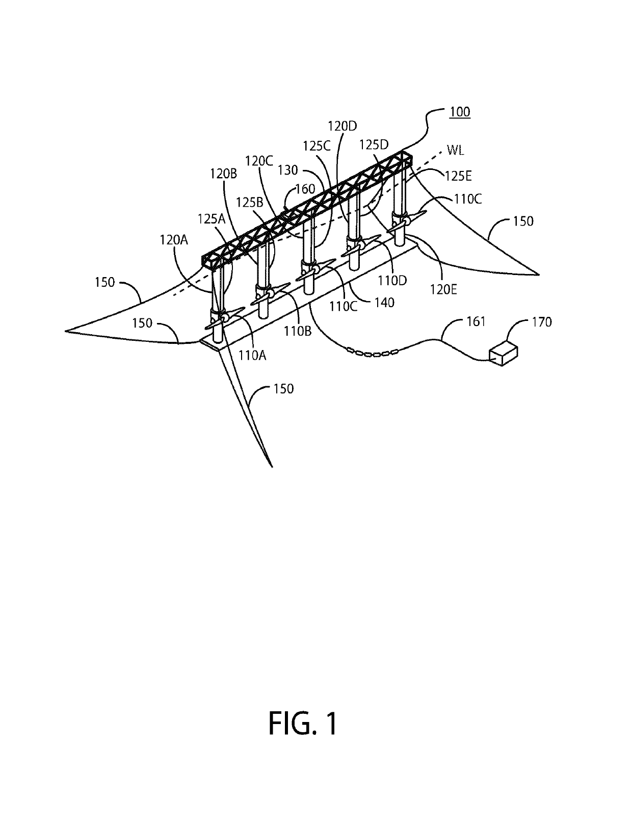
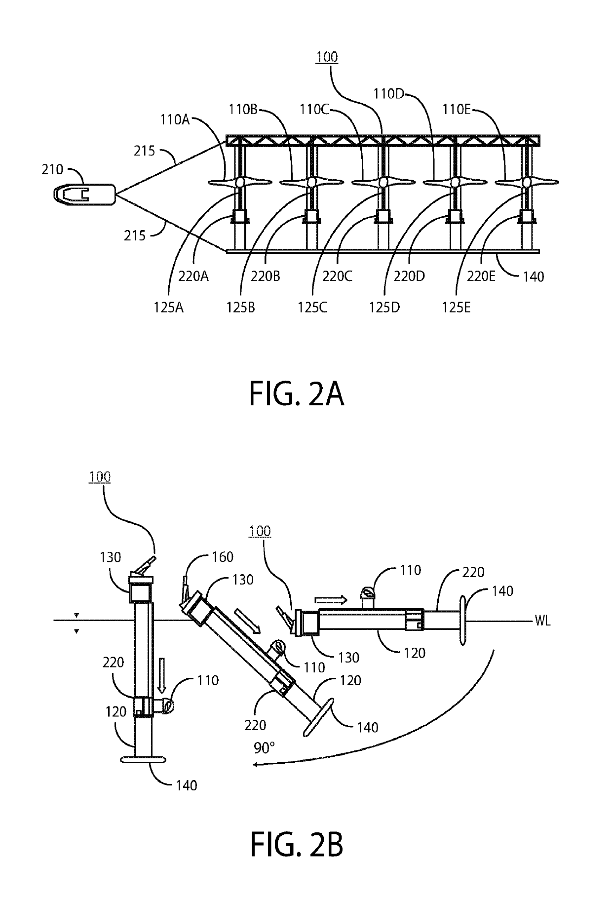
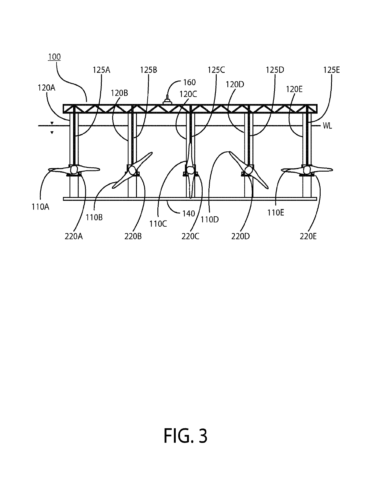
[0037]Preferred embodiments of the present invention and their advantages may be understood by referring to FIGS. 1-16, wherein like reference numerals refer to like elements. The present invention may be utilized in any type of moving liquid, e.g., water flow, environment such as, but not limited an ocean current environment or tidal current environment. Although the present invention is described in the context of electrical power generation, it can also be used to provide high pressure seawater for reverse osmosis fresh water production.

[0038]FIG. 1 illustrates an ocean current turbine system 100 according to an embodiment of the invention. The ocean current turbine system 100 comprises a plurality of current turbines 110A-E and respective floating spar / towers 120A-E, each turbine 110 disposed on its own spar / tower 120. The spar / towers 120A-E are located (when in operation) between a top structural connecting member 130 above the water line “WL” and a bottom structural connecting...


PUM


Abstract

The present invention describes a floating yawing spar buoy current / tidal turbine. The spar includes a spreader above the rotor(s) with the spreader tips connected to fore and aft cable yokes that transition to opposing mooring lines connected to anchors on the seabed. The spreader comprises a yaw motor, which drives gears that engage with a ring gear fixed to the outer perimeter of the spar.

Description

CROSS-REFERENCE TO RELATED APPLICATIONS[0001]The present invention is filed under 35 U.S.C. § 371 as the U.S. national phase of International Patent Application No. PCT / US2016 / 027004, filed Apr. 11, 2016, which designated the United States and which claims priority to U.S. patent application Ser. No. 14 / 682,700 filed Apr. 9, 2015, each of which is hereby incorporated in its entirety including all tables, figures and claims.BACKGROUND OF THE INVENTION[0002]1. Field of Invention[0003]The present invention is directed to turbine systems for the generation of electrical power and / or the production of fresh water from ocean tidal and / or current (gyre) flows, and more specifically, to a floating, yawing spar tidal turbine.[0004]2. Description of Related Art[0005]Ocean currents are a major, largely untapped energy resource. The potential for ocean current electric power generation in the United States is as much as 185 TWh / yr., comprising both tidal and gyre currents, which have the advant...

Claims


Application Information

Patent Timeline
Patent Type & Authority Patents(United States)
IPC IPC(8): F03B17/06F03B13/26B63B21/50B63B9/06
CPCF03B17/061F03B13/264B63B2009/067B63B2021/505F05B2210/404F05B2240/912Y02E10/28F05B2240/916F05B2240/93F05B2260/02F05B2260/503F05B2260/507F05B2270/20F05B2240/913Y02E10/30Y02E10/20
Inventor DEHLSEN, JAMES G. P.
Owner AQUANTIS
Why Eureka
Try Eureka